


Modern Agile teams thrive on speed, collaboration, and clear communication. Traditional UML modeling often gets in the way due to its steep learning curve and time-consuming manual drawing. By leveraging PlantUML and AI-powered tools, Agile teams can visualize architecture, interactions, and states in real-time, keeping pace with sprints and iterative development.
This guide explores key concepts, provides practical PlantUML examples, and demonstrates how to integrate these visual models into an Agile workflow.
1. Key Concept: Conversational Modeling for Rapid Prototyping
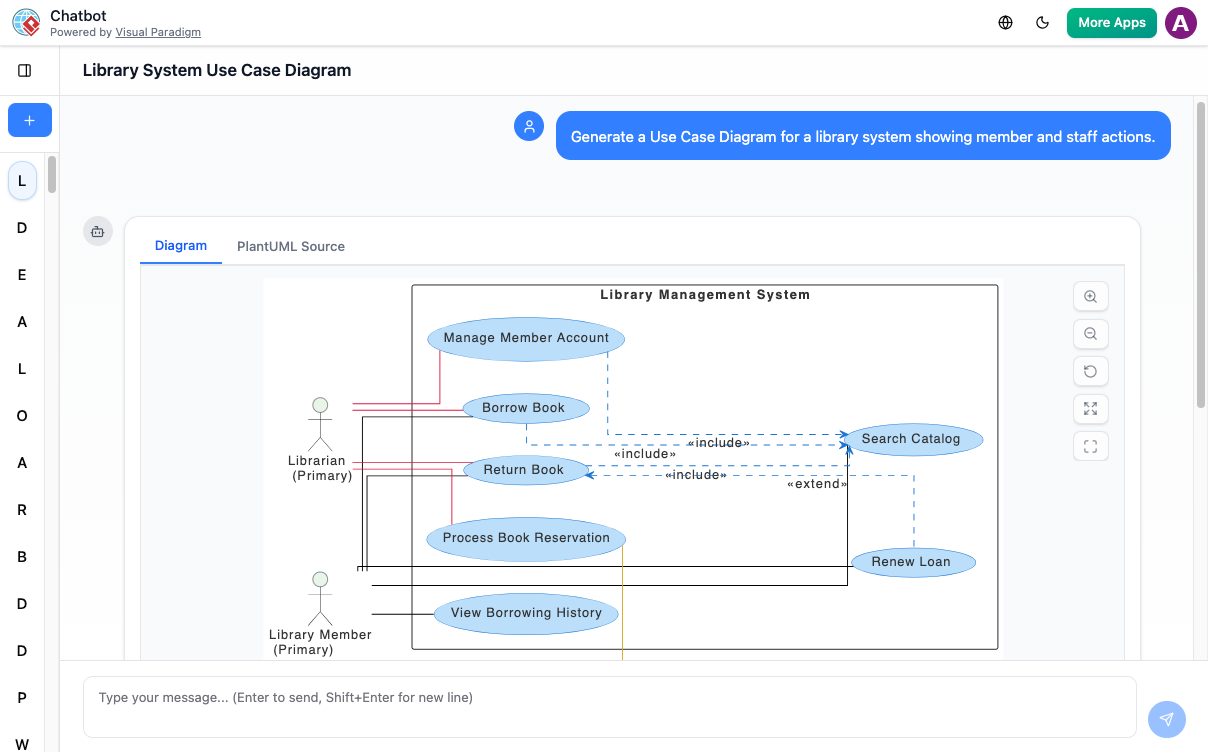
In an Agile environment, requirements evolve constantly. Conversational Modeling allows team members to describe system behaviors in plain English, with the AI generating the UML diagram instantly. This eliminates the need to master syntax immediately and allows non-technical stakeholders to participate in design sessions.
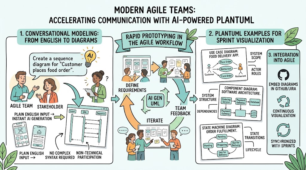
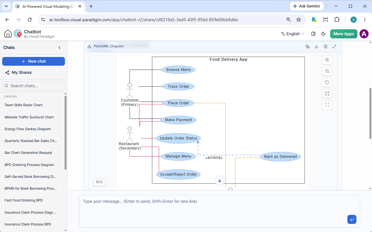
Instead of dragging boxes and connecting lines, you simply prompt: “Create a use case diagram for a food delivery app.” The AI interprets the intent, defines actors (Customer, Restaurant), and connects use cases (Place Order, Track Order) with appropriate relationships.
Example Workflow:
-
Prompt: “Draw a state diagram for a vending machine with states: Idle, Coin Inserted, Dispensing.”
-
Instant Generation: The tool renders the initial diagram.
-
Refinement: “Add a transition to ‘Out of Service’ if maintenance is needed.”
This approach turns design from a bottleneck into a collaborative dialogue.
2. Key Concept: Iterative Refinement and Version Awareness
Agile development is inherently iterative. A diagram generated in Sprint 1 is rarely perfect for Sprint 2. Iterative Refinement allows you to modify existing models through follow-up commands rather than redrawing from scratch.
The AI maintains the state of your diagram, understanding context like previous actors, relationships, and layout decisions. You can ask it to “Make the layout horizontal,” “Change all actors to red,” or “Add a database.” This ensures the model grows with the product.
Key Benefits:
-
Speed: Updates happen in seconds, not minutes.
-
Consistency: The AI ensures logical consistency (e.g., no orphaned relationships) during refactoring.
-
Traceability: Changes are often logged, allowing teams to see how the model evolved.
3. Key Concept: PlantUML as a Code-Based Standard
While chatbots generate diagrams visually, the underlying power for Agile teams lies in PlantUML—a text-based diagramming language. This allows diagrams to be treated as source code.
Why Code-Based Modeling Matters for Agile:
-
Version Control: Save
.plantumlfiles in Git. You can diff changes, roll back errors, and see exactly who changed a sequence diagram. -
CI/CD Integration: Automatically generate diagrams during build pipelines to keep documentation in sync with code.
-
Collaboration: Developers can edit diagram code in their IDE just like application code.
Example PlantUML using VPasCode Snippet:

@startuml
title E-Commerce Checkout Flow

actor Customer

package "Web Frontend" {
  actor "User Interface" as UI
}

package "Backend Services" {
  component "Order Service" as OS
  component "Payment Gateway" as PG
}

component "Order Confirmation" as OC

Customer --> UI
UI --> OS
OS --> PG
PG --> OS
OS --> OC
@enduml
By treating diagrams as code, teams ensure that documentation is never an afterthought but an integral part of the development lifecycle.
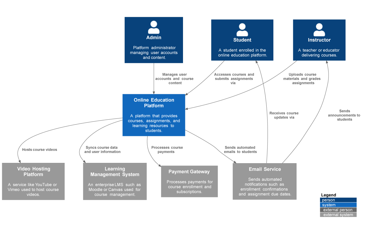
4. Key Concept: C4 Model for System Context and Clarity
The C4 Model (Context, Container, Component, Code) is a standardized approach to visualizing software architecture, highly recommended for Agile teams to manage complexity. It breaks down system design into four abstraction levels, making it easier to communicate with different stakeholders.
-
Level 1: System Context: Shows your system and its users (Actors) and external dependencies. Ideal for initial planning.
-
Level 2: Containers: Shows the high-level technical structure (e.g., Web App, Mobile App, Database, Microservices).
-
Level 3: Components: Breaks down containers into logical components (e.g., Authentication Service, Order Processor).
-
Level 4: Code: Details class structures (often generated automatically or less frequently used).
Using the C4 Model with PlantUML helps teams avoid “big design up front” (BDUF) while still providing a structured view that grows as the project scales.
5. Key Concept: Bi-Directional Synchronization (Model vs. Doc)
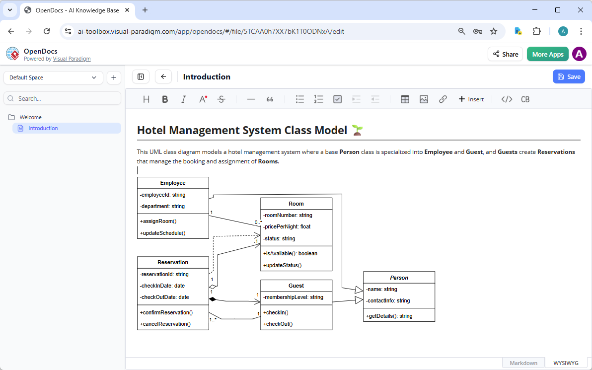
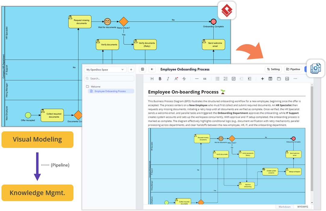
A common challenge in Agile is keeping documentation and the actual system in sync. Bi-Directional Synchronization bridges the gap between the visual model and the living documentation (e.g., OpenDocs, Wikis).
When a diagram is updated in the modeling tool, the changes propagate to the documentation automatically. Conversely, requirements written in the docs can trigger diagram updates. This ensures that when a Product Owner reviews a Jira ticket or a Confluence page, the attached diagram reflects the current system state.
Workflow Example:
-
Model: Architect updates a Sequence Diagram to reflect a new 2FA flow.
-
Sync: The diagram in OpenDocs updates automatically.
-
Doc: The developer reading the “API Integration Guide” sees the new flow immediately without manual copy-pasting.
6. Key Concept: Agile Workflow Integration and Collaboration
Modern UML modeling is not a siloed activity; it is deeply integrated into the Agile workflow. Teams use these models to facilitate Sprint Planning, Design Reviews, and Retrospectives.
-
Sprint Planning: Use a quick Use Case or Activity Diagram to clarify user stories and edge cases before development begins.
-
Design Reviews: Share a live PlantUML diagram during a review session. Stakeholders can suggest changes verbally, and the diagram updates in real-time.
-
Retrospectives: Analyze sequence diagrams to identify bottlenecks or single points of failure (e.g., “The payment gateway is a bottleneck”).
This integration fosters a culture where visual thinking is accessible to everyone, from the Scrum Master to the Lead Developer.
PlantUML Reference Examples Using VPasCode
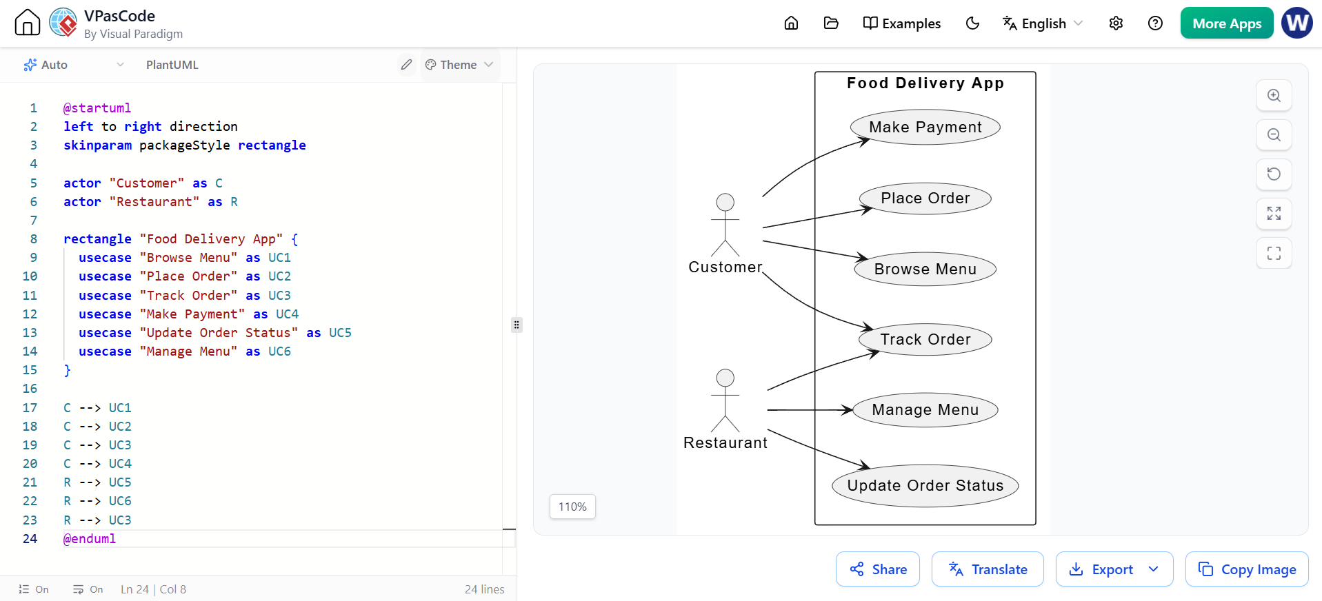
1. Use Case Diagram (Food Delivery App)
Concept: Defines actors and their interactions with the system.
@startuml
title E-Commerce Checkout Sequence

actor "Customer"
participant "Frontend"
participant "Cart Service"
participant "Inventory System"
participant "Payment Gateway"

"Customer" -> "Frontend": View Cart
"Frontend" -> "Cart Service": GetCart()
"Cart Service" -> "Inventory System": CheckStock([Items in Stock])
alt All items in stock
  "Cart Service" -> "Frontend": Show Total
  "Customer" -> "Frontend": Select Payment
  "Frontend" -> "Payment Gateway": ProcessPayment()
  "Payment Gateway" --> "Frontend": Success
  "Frontend" -> "Cart Service": ConfirmOrder()
else Out of stock
  "Cart Service" -> "Frontend": Show Error
end
@enduml
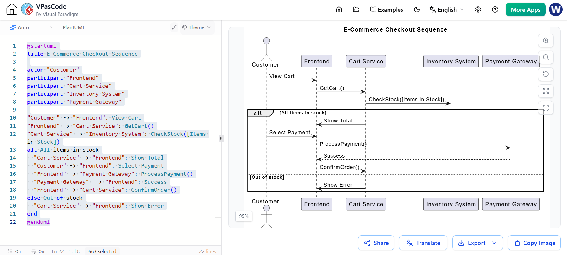
2. Sequence Diagram (Checkout Process)
Concept: Visualizes the interaction order between objects over time.
@startuml
title E-Commerce Checkout Sequence

actor "Customer"
participant "Frontend"
participant "Cart Service"
participant "Inventory System"
participant "Payment Gateway"

Customer -> Frontend: View Cart
Frontend -> Cart Service: GetCart()
Cart Service -> Inventory System: CheckStock([Items in Stock])
alt All items in stock
  Cart Service -> Frontend: Show Total
  Customer -> Frontend: Select Payment
  Frontend -> Payment Gateway: ProcessPayment()
  Payment Gateway --> Frontend: Success
  Frontend -> Cart Service: ConfirmOrder()
else Out of stock
  Cart Service -> Frontend: Show Error
end
@enduml
3. State Machine Diagram (Vending Machine)
Concept: Models the state transitions of a system based on events.
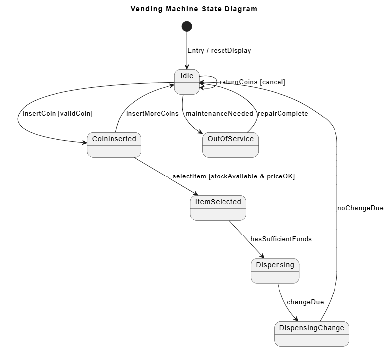
@startuml
title Vending Machine State Diagram

[*] --> Idle: Entry / resetDisplay
Idle --> CoinInserted: insertCoin [validCoin]
CoinInserted --> ItemSelected: selectItem [stockAvailable & priceOK]
ItemSelected --> Dispensing: hasSufficientFunds
Dispensing --> DispensingChange: changeDue
DispensingChange --> Idle: noChangeDue
CoinInserted --> Idle: insertMoreCoins
Idle --> Idle: returnCoins [cancel]
Idle --> OutOfService: maintenanceNeeded
OutOfService --> Idle: repairComplete
@enduml
4. Class Diagram (Library Management)
Concept: Shows static structure, classes, and relationships.
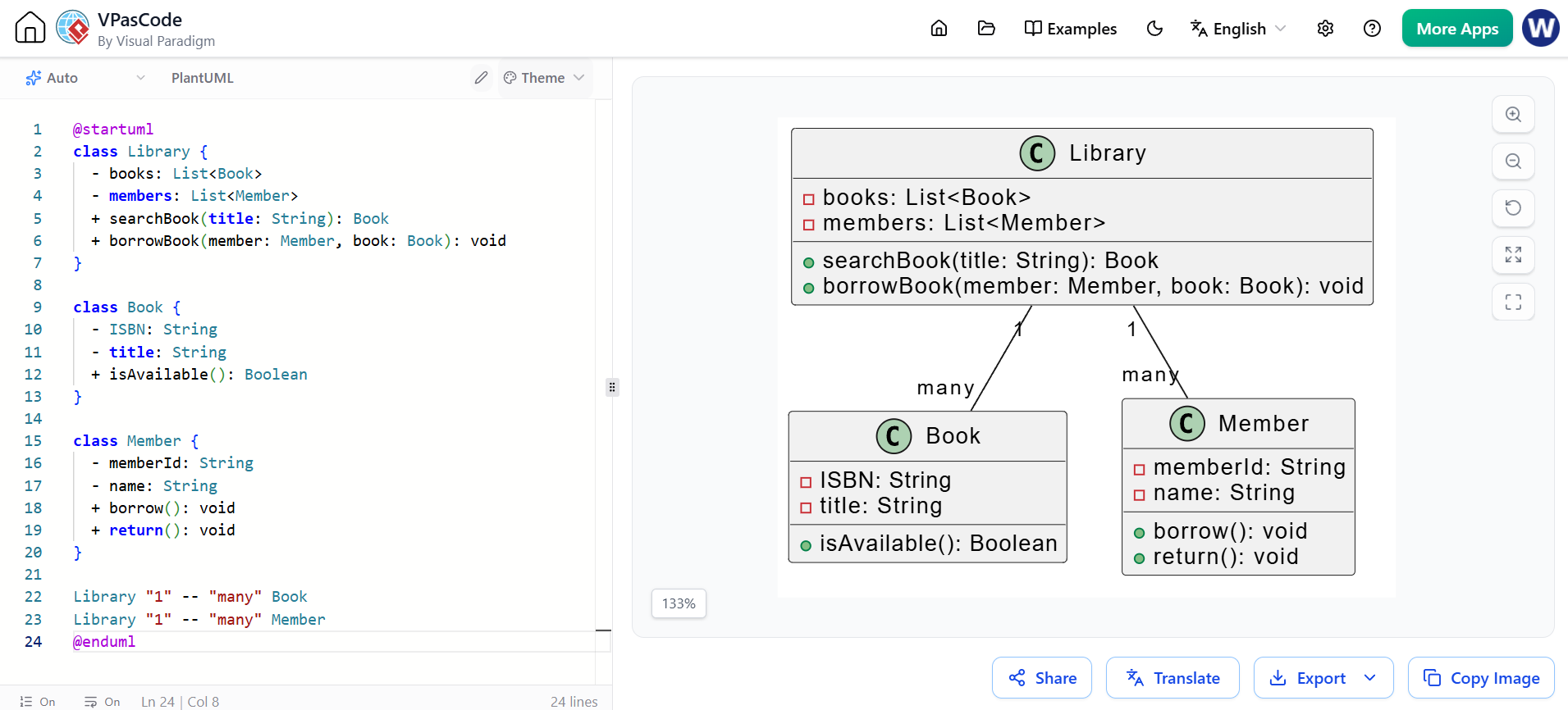
@startuml
class Library {
  - books: List<Book>
  - members: List<Member>
  + searchBook(title: String): Book
  + borrowBook(member: Member, book: Book): void
}

class Book {
  - ISBN: String
  - title: String
  + isAvailable(): Boolean
}

class Member {
  - memberId: String
  - name: String
  + borrow(): void
  + return(): void
}

Library "1" -- "many" Book
Library "1" -- "many" Member
@enduml
5. C4 Container Diagram (E-Commerce Platform)
Concept: High-level architecture view showing containers.
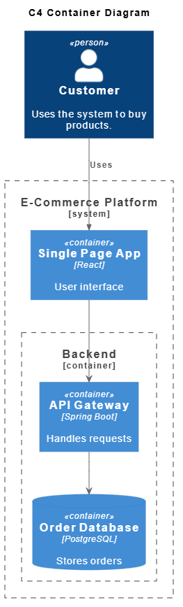
@startuml
title C4 Container Diagram

!include <C4/C4_Container>

Person(customer, "Customer", "Uses the system to buy products.")

System_Boundary(b1, "E-Commerce Platform") {
  Container(spa, "Single Page App", "React", "User interface")
  Container_Boundary(b2, "Backend") {
    Container(api, "API Gateway", "Spring Boot", "Handles requests")
    ContainerDb(db, "Order Database", "PostgreSQL", "Stores orders")
  }
}

spa --> api
api --> db

Rel(customer, spa, "Uses")
@enduml
6. Deployment Diagram (Cloud Infrastructure)
Concept: Shows physical deployment of software components on hardware.
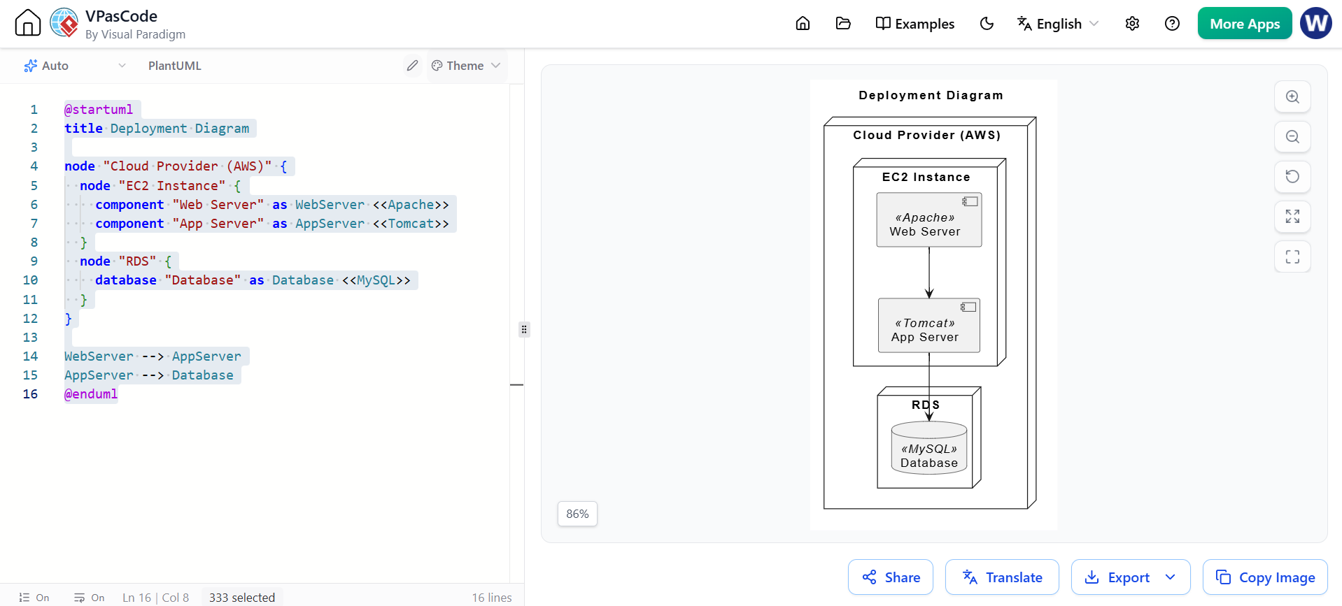
@startuml
title Deployment Diagram

node "Cloud Provider (AWS)" {
  node "EC2 Instance" {
    component "Web Server" as WebServer <>
    component "App Server" as AppServer <>
  }
  node "RDS" {
    database "Database" as Database <>
  }
}

WebServer --> AppServer
AppServer --> Database
@enduml