


Introduction
In systems analysis, the most persistent source of scope creep, premature optimization, and stakeholder misalignment is not a lack of technical skill—it is the conflation of what a system must do with how it will be built. This confusion manifests directly in the Data Flow Diagram (DFD). While hierarchy (Context, Level 1, Level 2) defines the granularity of a model, the distinction between Logical DFDs and Physical DFDs defines its intent.
These two dimensions are orthogonal. A Context Diagram can be physical; a Level 3 diagram can be logical. Treating “logical” as synonymous with “high-level” and “physical” as synonymous with “detailed” is a fundamental error that undermines the analytical power of the DFD.
This guide provides a comprehensive, standalone reference for mastering the Logical/Physical axis. It establishes precise definitions, delineates strict transformation rules, identifies common anti-patterns, and demonstrates how maintaining this separation serves as the primary defense against architectural debt. Whether you are eliciting business requirements or specifying microservice contracts, understanding this dichotomy is the difference between a DFD that captures enduring business truth and one that merely documents a transient technical implementation.
1. Core Definitions: Orthogonality of Intent and Granularity
Before examining the models individually, we must establish the coordinate system. DFD quality depends on two independent axes:
| Axis | Question Answered | Values | Governs |
|---|---|---|---|
| Hierarchy (Level) | How detailed is the view? | Context (0), Level 1, Level 2… Functional Primitive | Decomposition depth; numbering tree |
| Intent (Type) | What is the modeling purpose? | Logical, Physical | Abstraction from or commitment to implementation |
The Critical Insight: You can—and often should—produce a Logical Level 2 DFD (detailed business process, no technology) and a Physical Context Diagram (system boundary defined by specific APIs and protocols). These are not contradictions; they are different views serving different stakeholders at different times.
1.1 Logical DFD: The Business Truth
A Logical DFD models the essential business function, stripped of all implementation bias. It represents what the organization must do to fulfill its mission, regardless of whether the work is performed by humans, paper forms, mainframes, or AI agents.
-
Vocabulary: Business activities (
Validate Creditworthiness), conceptual data (Customer Record,Order), organizational roles (Credit Analyst). -
Excludes: Database names, API protocols, file formats, hardware, software vendors, automation decisions, timing constraints, departmental silos (unless functionally relevant).
-
Stability: High. Business rules change slowly; technology changes rapidly. A well-crafted Logical DFD remains valid across multiple technology generations.
-
Primary Audience: Business stakeholders, domain experts, product owners, auditors.
1.2 Physical DFD: The Technical Realization
A Physical DFD models the concrete implementation of the logical requirements. It specifies exactly how data moves through specific technologies, people, and infrastructure.
-
Vocabulary: Services (
CreditCheckService v2.1), schemas (postgres.customers), protocols (HTTPS/JSON,Kafka topic: credit-events), files (/var/log/audit.csv), specific job titles or departments. -
Includes: All technology choices, manual vs. automated splits, batch vs. real-time distinctions, error handling mechanisms, security controls, integration points.
-
Stability: Low. Tied directly to the current technology stack and organizational structure. Expected to evolve with each release cycle.
-
Primary Audience: Architects, developers, DevOps engineers, QA testers.
2. The Logical DFD in Depth: Capturing Enduring Requirements
The Logical DFD is the foundation of rigorous systems analysis. Without it, Physical DFDs become unanchored technical sketches that cannot be validated against business need.
2.1 Characteristics of a Well-Formed Logical DFD
-
Process Names Are Pure Business Verbs:
Calculate Tax Liability, notInvoke TaxCalcAPI.Notify Customer of Delay, notSend SQS Message. -
Data Stores Are Conceptual:
D1 Customer,D2 Order History—neverMySQL customers_tblorS3 bucket orders-archive. -
External Entities Are Business Actors:
Regulatory Body,Shipping Partner—notIRS REST EndpointorFedEx SOAP Gateway. -
Flows Describe Information Content:
Tax Assessment Result, notJSON payload with field tax_amount. -
No Technology Leakage: Zero references to databases, message queues, programming languages, frameworks, cloud providers, or network protocols.
-
Manual Processes Are Included: If a human currently performs a step, it appears as a process. The Logical DFD documents current business reality, not aspirational automation.
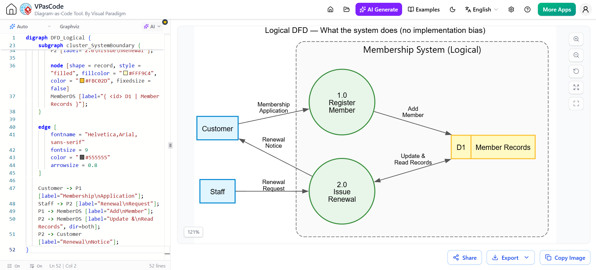
2.2 Example: Logical Membership System (Level 1)
digraph DFD_Logical {
    graph [
        rankdir = LR
        splines = true
        overlap = false
        nodesep = 0.5
        ranksep = 0.8
        fontname = "Helvetica,Arial,sans-serif"
        fontsize = 12
        label = "Logical DFD — What the system does (no implementation bias)"
        labelloc = t
    ]

    node [
        fontname = "Helvetica,Arial,sans-serif"
        fontsize = 11
        penwidth = 1.5
    ]

    node [shape = box, style = "filled", fillcolor = "#E1F5FE", color = "#0288D1"]
    Customer; Staff;

    subgraph cluster_SystemBoundary {
        label = "Membership System (Logical)";
        fontname = "Helvetica,Arial,sans-serif; bold"
        fontsize = 14
        color = "#757575"
        style = "dashed,rounded"
        bgcolor = "#FAFAFA"
        margin = 20

        node [shape = circle, style = "filled", fillcolor = "#E8F5E9", color = "#388E3C", fixedsize = true, width = 1.4]
        P1 [label="1.0\nRegister\nMember"];
        P2 [label="2.0\nIssue\nRenewal"];

        node [shape = record, style = "filled", fillcolor = "#FFF9C4", color = "#FBC02D", fixedsize = false]
        MemberDS [label="{ <id> D1 | Member Records }"];
    }

    edge [
        fontname = "Helvetica,Arial,sans-serif"
        fontsize = 9
        color = "#555555"
        arrowsize = 0.8
    ]

    Customer -> P1 [label="Membership\nApplication"];
    Staff -> P2 [label="Renewal\nRequest"];
    P1 -> MemberDS [label="Add\nMember"];
    P2 -> MemberDS [label="Update &\nRead Records", dir=both];
    P2 -> Customer [label="Renewal\nNotice"];
}
Key Observations:
-
Process
1.0 Register Membersays nothing about web forms, APIs, or database inserts. It could be fulfilled by a paper form filed in a cabinet. -
Data store
D1 Member Recordsis a business concept, not a schema. -
The flow
Membership Applicationdescribes information, not a protocol. -
Both
CustomerandStaffare business roles, not system interfaces.
2.3 When to Use Logical DFDs
-
Requirements Elicitation: Stakeholders validate business correctness without being distracted or intimidated by technology.
-
Gap Analysis: Comparing current-state (as-is) Logical DFDs with future-state (to-be) Logical DFDs reveals pure business process improvements independent of technology.
-
Regulatory Compliance: Auditors care about what controls exist, not which framework implements them.
-
Vendor Selection: Evaluating COTS/SaaS solutions against a technology-neutral specification prevents vendor lock-in during evaluation.
-
Onboarding New Team Members: Understanding business intent before diving into code reduces ramp-up time and prevents “cargo cult” maintenance.
3. The Physical DFD in Depth: Specifying Technical Reality
The Physical DFD is the bridge between validated business requirements and executable system design. It is derived from the Logical DFD, never created in isolation.
3.1 Characteristics of a Well-Formed Physical DFD
-
Process Names Reflect Implementation Units:
RegisterService.handlePOST(),BatchRenewalJob,ManualReviewQueueProcessor. -
Data Stores Are Concrete Artifacts:
D1 postgres.members_db,D2 Redis.session_cache,D3 S3.document_archive,D4 PaperFile.Room204. -
External Entities Are Specific Interfaces:
Stripe Payment API v2024-06,HRIS LDAP Server,Operator Console (React SPA). -
Flows Specify Protocols and Formats:
HTTPS POST /api/v1/register (JSON Schema v3),Kafka Event: member.registered (Avro),SMTP Email (HTML Template #47). -
Manual/Automated Split Is Explicit: Human-performed processes are clearly distinguished from automated services. Manual steps include the responsible role/department.
-
Infrastructure Awareness: Load balancers, caches, message brokers, and batch schedulers appear as processes or stores when they materially affect data flow.
-
Error and Exception Paths Are Modeled: Retry queues, dead-letter stores, fallback services, and alerting flows are first-class elements.
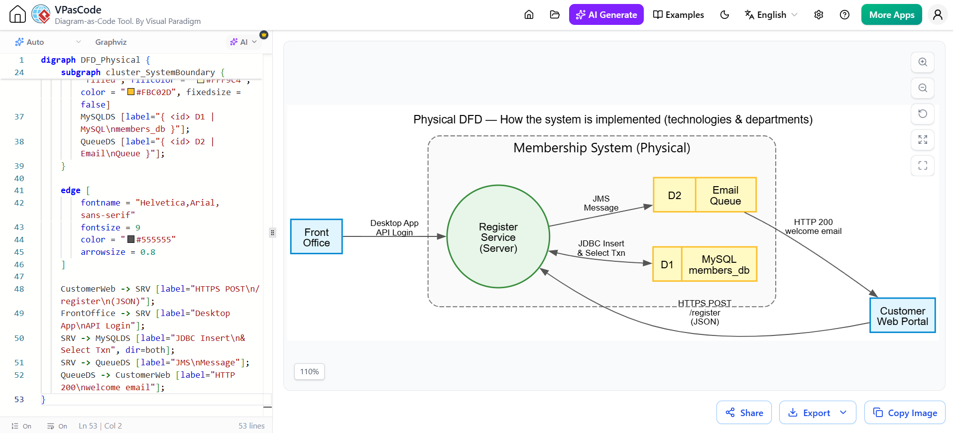
3.2 Example: Physical Membership System (Level 1)
digraph DFD_Physical {
    graph [
        rankdir = LR
        splines = true
        overlap = false
        nodesep = 0.5
        ranksep = 0.8
        fontname = "Helvetica,Arial,sans-serif"
        fontsize = 12
        label = "Physical DFD — How the system is implemented (technologies & departments)"
        labelloc = t
    ]

    node [
        fontname = "Helvetica,Arial,sans-serif"
        fontsize = 11
        penwidth = 1.5
    ]

    node [shape = box, style = "filled", fillcolor = "#E1F5FE", color = "#0288D1"]
    CustomerWeb [label="Customer\nWeb Portal"];
    FrontOffice [label="Front\nOffice"];

    subgraph cluster_SystemBoundary {
        label = "Membership System (Physical)";
        fontname = "Helvetica,Arial,sans-serif; bold"
        fontsize = 14
        color = "#757575"
        style = "dashed,rounded"
        bgcolor = "#FAFAFA"
        margin = 20

        node [shape = circle, style = "filled", fillcolor = "#E8F5E9", color = "#388E3C", fixedsize = true, width = 1.5]
        SRV [label="Register\nService\n(Server)"];

        node [shape = record, style = "filled", fillcolor = "#FFF9C4", color = "#FBC02D", fixedsize = false]
        MySQLDS [label="{ <id> D1 | MySQL\nmembers_db }"];
        QueueDS [label="{ <id> D2 | Email\nQueue }"];
    }

    edge [
        fontname = "Helvetica,Arial,sans-serif"
        fontsize = 9
        color = "#555555"
        arrowsize = 0.8
    ]

    CustomerWeb -> SRV [label="HTTPS POST\n/register\n(JSON)"];
    FrontOffice -> SRV [label="Desktop App\nAPI Login"];
    SRV -> MySQLDS [label="JDBC Insert\n& Select Txn", dir=both];
    SRV -> QueueDS [label="JMS\nMessage"];
    QueueDS -> CustomerWeb [label="HTTP 200\nwelcome email"];
}
Key Observations:
-
Register Service (Server)replacesRegister Member—the business verb becomes a deployable unit. -
MySQL members_dbandEmail Queuereplace the conceptualMember Recordsstore—the single logical store decomposes into multiple physical artifacts. -
Flows specify
HTTPS POST,JDBC, andJMS—protocols are now explicit. -
Customer Web PortalandFront Office Desktop Appdistinguish access channels that were unified underCustomerandStaffin the logical model. -
The welcome email now flows through the queue, exposing asynchronous behavior invisible in the logical model.
3.3 When to Use Physical DFDs
-
Architecture Design: Translating validated business requirements into service boundaries, data persistence strategies, and integration patterns.
-
Implementation Planning: Developers use Physical DFDs as direct blueprints for coding, configuration, and infrastructure provisioning.
-
Performance Modeling: Identifying bottlenecks, cache opportunities, and async boundaries requires physical detail.
-
Security Review: Threat modeling operates on physical attack surfaces—specific endpoints, protocols, and storage mechanisms.
-
Operational Runbooks: Incident response and monitoring depend on knowing exact data paths, failure modes, and recovery procedures.
-
Migration Planning: Comparing old and new Physical DFDs reveals precise cutover points, data migration needs, and parallel-run requirements.
4. The Transformation: Deriving Physical from Logical
The relationship between Logical and Physical DFDs is derivational, not parallel. Every element in a Physical DFD must trace back to one or more elements in the corresponding Logical DFD. Untraceable physical elements indicate either gold-plating or undocumented business requirements.
4.1 Transformation Rules
| Logical Element | Physical Transformation | Rationale |
|---|---|---|
| Business Process | One or more services/functions/jobs/manual steps | Automation may split, merge, or redistribute business functions |
| Conceptual Data Store | One or more databases/files/caches/queues | Normalization, performance, and durability requirements fragment logical stores |
| Business Data Flow | Protocol-specific message/stream/file transfer | Information must be serialized, secured, and transported |
| Business External Entity | Specific interface/system/person | Abstract actors resolve to concrete integration points |
| Implicit Business Rule | Explicit validation/transformation logic | Rules that were assumed in business context must be coded |
4.2 Common Transformations Illustrated
One Logical Process → Multiple Physical Services:
Logical Process Payment might decompose physically into PaymentGatewayAdapter, FraudDetectionService, LedgerWriteService, and ReceiptEmailJob. The business function is singular; the implementation is distributed.
One Logical Store → Multiple Physical Stores:
Logical D1 Order might become postgres.orders (transactional), Redis.order_cache (read performance), S3.order_documents (attachments), and Elasticsearch.order_search (full-text search). Each serves a different non-functional requirement while representing the same business entity.
One Logical Flow → Multiple Physical Transports:
Logical Order Confirmation might be delivered via HTTPS Response (synchronous acknowledgment), Kafka Event (downstream processing), and SMTP Email (customer notification). The business intent is singular; the delivery mechanism is multi-modal.
4.3 Traceability Matrix
Maintain an explicit mapping document:
| Logical Element | Physical Element(s) | Transformation Notes |
|---|---|---|
1.0 Register Member |
RegisterService.handlePOST() |
Automated; synchronous |
2.0 Issue Renewal |
BatchRenewalJob + ManualReviewQueueProcessor |
Split: auto-renewal + exception handling |
D1 Member Records |
postgres.members_db + Redis.member_session |
Primary store + session cache |
Membership Application |
HTTPS POST /api/v1/register (JSON) |
RESTful API contract |
Renewal Notice |
SMTP (Template #47) + InAppNotification |
Multi-channel delivery |
Without this matrix, Physical DFDs drift from business intent. Audits, refactoring, and onboarding all depend on traceability.
5. Anti-Patterns: Recognizing and Correcting Common Failures
5.1 Premature Physicalization
Symptom: Logical DFDs contain database names, API versions, or cloud service references.
Cause: Analysts default to known technology; stakeholders lack patience for abstraction.
Impact: Requirements become coupled to current stack; re-evaluation of alternatives is impossible; business reviewers disengage.
Correction: Enforce a “technology vocabulary ban” during logical modeling sessions. Use a glossary of approved business terms. Review logical DFDs with non-technical stakeholders before any physical work begins.
5.2 Orphaned Physical Elements
Symptom: Physical DFD contains services, stores, or flows with no corresponding logical ancestor.
Cause: Developers add “helpful” infrastructure without business justification; legacy components persist without documented purpose.
Impact: Gold-plating; increased attack surface; maintenance burden; compliance gaps.
Correction: Require traceability matrix entry for every physical element. Unmapped elements must be justified as cross-cutting concerns (logging, monitoring, security) or removed.
5.3 False Equivalence of Levels and Types
Symptom: Team refers to “Logical = Context/Level 1” and “Physical = Level 2+.”
Cause: Misunderstanding orthogonality; conflating abstraction with granularity.
Impact: Detailed business processes never modeled logically; high-level technical architecture never modeled physically.
Correction: Train team on the two-axis model. Produce at least one example of a Logical Level 2 and a Physical Context Diagram to break the mental association.
5.4 Synchronized Decay
Symptom: Logical DFD updated but Physical DFD not regenerated (or vice versa).
Cause: No formal change propagation process; models treated as disposable artifacts.
Impact: Documentation lies; new team members learn incorrect system behavior; audits fail.
Correction: Treat DFD pairs as versioned, linked artifacts. CI pipeline validates traceability matrix on every commit. Model review required for both types on any change.
5.5 Missing Manual Processes in Logical Models
Symptom: Logical DFD shows only automated flows; current-state human work is invisible.
Cause: Analyst assumes future state; embarrassment about manual workarounds.
Impact: Automation misses critical business knowledge; transition planning fails; user resistance.
Correction: Mandate current-state Logical DFD includes all manual steps. Annotate pain points and error rates. Future-state Logical DFD explicitly marks processes targeted for automation vs. retention.
6. Quality Checklist: Validating Logical and Physical DFDs
Apply these gates independently to each model type.
6.1 Logical DFD Checklist
-
Zero technology references: No DBMS, protocols, file formats, vendors, or infrastructure mentioned.
-
Business verb-noun naming: All processes named with business action + business object.
-
Conceptual stores only: Data stores represent business entities, not schemas or files.
-
Complete current-state coverage: Manual processes, workarounds, and exception paths included.
-
Stakeholder validation signed off: Business owner confirms accuracy without technical translation.
-
Balanced against parent level: Inputs/outputs match parent process exactly.
-
Functional primitives reachable: Every leaf process describable in business pseudocode.
6.2 Physical DFD Checklist
-
Full traceability to Logical DFD: Every element maps to logical ancestor via traceability matrix.
-
Concrete implementation vocabulary: Specific technologies, protocols, schemas, and interfaces named.
-
Manual/automated split explicit: Human-performed steps identified with responsible role.
-
Non-functional requirements reflected: Caching, queuing, replication, and security controls modeled where they affect data flow.
-
Error and exception paths included: Retry, dead-letter, fallback, and alerting flows present.
-
Balanced against parent level: Inputs/outputs match parent process exactly.
-
Infrastructure-aware: Load balancers, brokers, and schedulers included when material to flow.
6.3 Cross-Model Consistency Checklist
-
Orthogonality maintained: Level and Type axes treated independently; no false equivalences.
-
Change propagation enforced: Updates to one model trigger review/update of the other.
-
Version alignment: Logical and Physical DFDs at same level share version identifier.
-
Glossary consistency: Business terms in Logical DFD map to technical terms in Physical DFD via shared dictionary.
-
Stakeholder-appropriate audience: Logical reviewed by business; Physical reviewed by engineering; cross-review at integration points.
7. Conclusion: The Strategic Value of Separation
The discipline of maintaining separate Logical and Physical DFDs is not academic pedantry—it is a strategic risk management practice. Organizations that conflate these models accumulate three forms of debt:
-
Requirements Debt: Business intent is lost in technical detail, leading to systems that work correctly but solve the wrong problem.
-
Architecture Debt: Technology choices become invisible assumptions, making migration, scaling, and compliance exponentially harder.
-
Knowledge Debt: Institutional understanding of why the system exists decays as personnel turnover outpaces documentation updates.
By treating Logical and Physical DFDs as orthogonal, derivational, and independently versioned artifacts, you create a durable knowledge infrastructure. The Logical DFD becomes the organization’s enduring statement of business truth—a stable reference point that survives technology refreshes, regulatory changes, and team transitions. The Physical DFD becomes a precise, traceable engineering specification that can be confidently built, tested, operated, and evolved.
The effort required to maintain this separation pays compound returns. Every hour invested in clarifying business intent without technical noise saves ten hours of rework, miscommunication, and architectural remediation downstream. In an era of rapid technological change, the ability to distinguish what must remain constant from what is free to evolve is not just good analysis—it is organizational resilience.
Use the definitions, transformation rules, anti-patterns, and checklists in this guide as your standard. Build Logical DFDs first, validate them ruthlessly with business stakeholders, derive Physical DFDs with full traceability, and maintain both with disciplined change control. The result will be systems that are not only technically sound but authentically aligned with the business they serve.