


Introduction
In object-oriented software engineering, the Class Diagram is the most ubiquitous yet frequently misapplied artifact. Often reduced to a mere database schema in UML notation or treated as a direct 1:1 map of code structure, a true Class Diagram is a rigorous specification of static structure, type contracts, and semantic relationships. It is the architectural blueprint that bridges the gap between business domain concepts and executable software design.
Despite the dominance of agile methodologies and test-driven development, the Class Diagram remains the gold standard for defining API contracts, validating domain models with stakeholders, and ensuring structural integrity before implementation begins. However, producing a professional-grade Class Diagram requires more than drawing boxes and arrows. It demands strict adherence to abstraction levels (Conceptual, Logical, Physical), a precise understanding of relationship semantics (association vs. aggregation vs. composition), and disciplined application of SOLID principles to prevent structural decay.
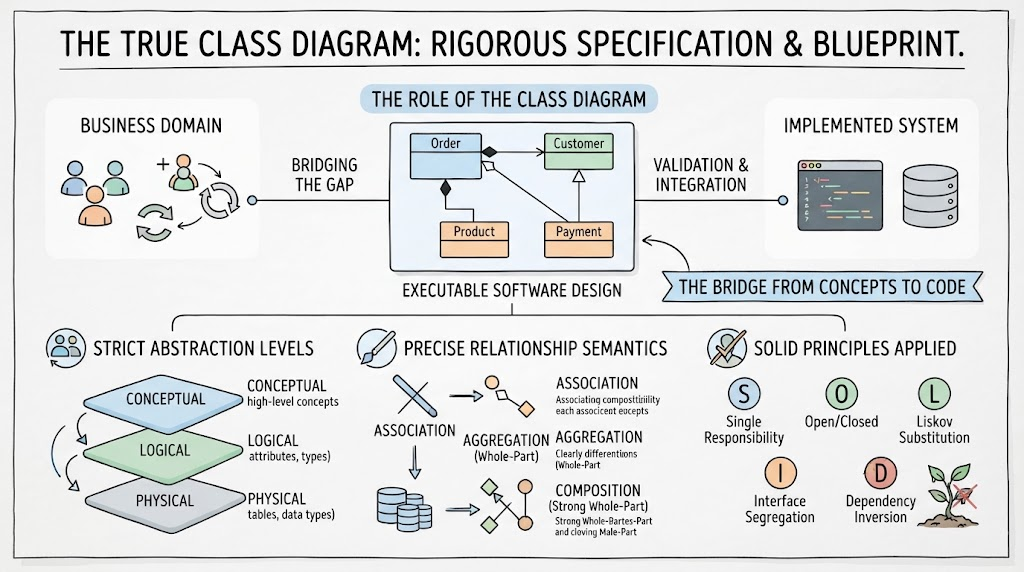
This guide provides a comprehensive reference for Class Diagram vocabulary, abstraction hierarchy, relationship rules, and quality invariants. Whether you are modeling a complex Order Management domain or designing a microservice API contract, the following sections establish the precise framework needed to create Class Diagrams that are analytically sound, architecturally robust, and practically useful. All examples are rendered using PlantUML, providing executable specifications that can be version-controlled and integrated into CI/CD pipelines.
1. The Core Building Blocks: The Class Diagram “Vocabulary”
Before addressing abstraction levels, you must master the fundamental elements. These are consistent across UML 2.x standards but differ significantly in semantic intent depending on the abstraction level.
| Element | Purpose | Notation | Key Constraint |
|---|---|---|---|
| Class | A blueprint for objects; encapsulates state (attributes) and behavior (methods) | Rectangle with 3 compartments (Name, Attributes, Operations) | Name must be singular noun; attributes typed; visibility marked (+, -, #) |
| Interface | A contract specifying behavior without implementation | Rectangle with «interface» stereotype or lollipop notation | No attributes (except constants); all operations public abstract |
| Enumeration | A fixed set of named values | Rectangle with «enumeration» stereotype | Values listed in name compartment; no operations typically |
| Association | Structural relationship indicating objects are connected | Solid line with optional multiplicity | Must have role names at both ends for clarity; multiplicity mandatory |
| Aggregation | Weak “has-a” relationship; part can exist independently | Solid line with hollow diamond at whole end | Part lifecycle independent of whole; shared ownership possible |
| Composition | Strong “owns-a” relationship; part cannot exist without whole | Solid line with filled diamond at whole end | Part lifecycle bound to whole; exclusive ownership |
| Inheritance | “Is-a” relationship; subclass inherits structure/behavior | Solid line with hollow triangle pointing to parent | Liskov Substitution Principle must hold; avoid deep hierarchies |
| Realization | “Implements” relationship; class fulfills interface contract | Dashed line with hollow triangle pointing to interface | Class must implement all interface operations |
| Dependency | “Uses” relationship; temporary or weak coupling | Dashed open arrow | Minimize; indicates potential refactoring target |
Naming Conventions (Crucial for Clarity)
-
Classes: Singular PascalCase nouns →
Order,CustomerProfile,PaymentGateway. Never plural (Orders) or verb-based (ProcessOrder). -
Attributes: camelCase + type →
orderId: UUID,createdAt: DateTime. Visibility prefix mandatory:+public,-private,#protected. -
Operations: camelCase verb phrase + return type →
+calculateTotal(): Decimal,-validateAddress(): Boolean. Parameters typed:(quantity: Integer, price: Decimal). -
Relationships: Role names at both ends →
Customer [1] places [0..*] Order. Multiplicity always specified:1,0..1,0..*,1..*,n..m.
2. The Abstraction Hierarchy: Conceptual, Logical, Physical
The most critical dimension in Class Diagram modeling is abstraction level. Confusing these levels is the primary source of model failure. Each level serves distinct stakeholders and purposes. They are not sequential steps to be discarded but parallel views maintained throughout the lifecycle.
2.1 Conceptual Class Diagram: The Domain Truth
-
Focus: Business entities, relationships, and rules independent of any technology or implementation.
-
Deliberately Ignores: Programming languages, databases, frameworks, APIs, performance concerns, serialization formats.
-
Attributes: Business-meaningful properties only. No IDs unless business-relevant (e.g.,
ssn,isbn). No foreign keys. -
Methods: Rarely shown. If present, represent business behaviors (
calculateDiscount(),isEligibleForRenewal()), not getters/setters. -
Relationships: Reflect real-world semantics. Multiplicities reflect business rules, not storage constraints.
-
Stakeholders: Domain experts, business analysts, product owners, auditors.
-
Stability: High. Changes only when business understanding evolves.
Example: Conceptual Order Domain
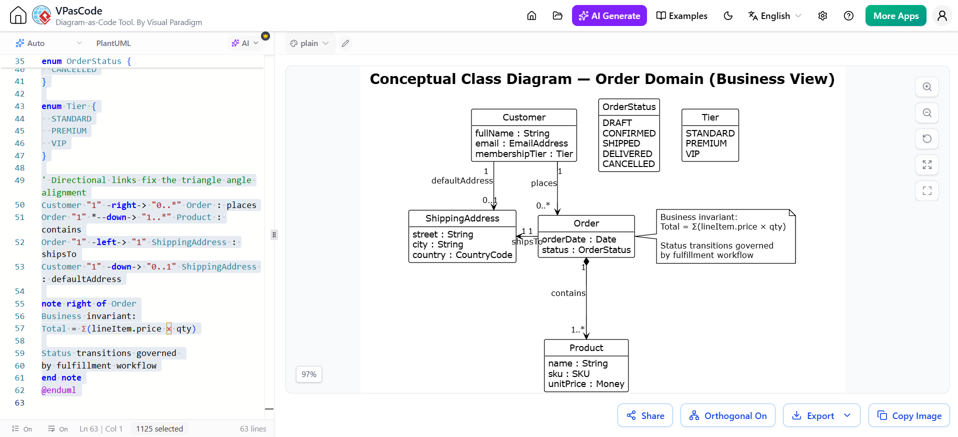
@startuml conceptual-order-domain
!theme plain
skinparam linetype ortho
skinparam classAttributeIconSize 0
hide circle
hide methods

title Conceptual Class Diagram — Order Domain (Business View)

class Customer {
  fullName : String
  email : EmailAddress
  membershipTier : Tier
}

class Order {
  orderDate : Date
  status : OrderStatus
  +calculateTotal() : Money
  +isShippable() : Boolean
}

class Product {
  name : String
  sku : SKU
  unitPrice : Money
}

class ShippingAddress {
  street : String
  city : String
  country : CountryCode
}

enum OrderStatus {
  DRAFT
  CONFIRMED
  SHIPPED
  DELIVERED
  CANCELLED
}

enum Tier {
  STANDARD
  PREMIUM
  VIP
}

' Directional links fix the triangle angle alignment
Customer "1" -right-> "0..*" Order : places
Order "1" *--down-> "1..*" Product : contains
Order "1" -left-> "1" ShippingAddress : shipsTo
Customer "1" -down-> "0..1" ShippingAddress : defaultAddress

note right of Order
Business invariant:
Total = Σ(lineItem.price × qty)

Status transitions governed
by fulfillment workflow
end note
@enduml
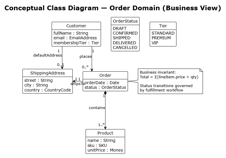
Key Observations:
-
No IDs, no FKs, no persistence annotations.
-
Methods express business logic, not data access.
-
Multiplicities reflect business rules (
Ordermust contain at least oneProduct). -
Composition (
*--) used where business semantics demand it (line items cannot exist without order). -
Enumerations capture business vocabularies, not technical codes.
2.2 Logical Class Diagram: The Software Specification
-
Focus: Platform-independent software design. Defines types, interfaces, and contracts without committing to specific technologies.
-
Includes: Abstract classes, interfaces, generic types, design patterns, error handling types.
-
Attributes: Typed with platform-neutral types (
String,Decimal,DateTime,UUID). Includes identity attributes (id) and derived attributes (/total). -
Methods: Full signatures including parameters, return types, exceptions. Getters/setters omitted unless behaviorally significant.
-
Relationships: Precise multiplicities, navigability arrows, role names. Interfaces realized explicitly.
-
Stakeholders: Architects, senior developers, API designers.
-
Stability: Medium. Evolves with design refinement but stable across implementation choices.
Example: Logical Order Service Design
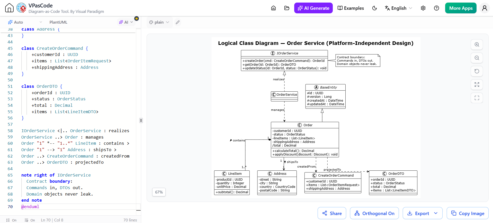
@startuml logical-order-service
!theme plain
skinparam linetype ortho
skinparam classAttributeIconSize 0

title Logical Class Diagram — Order Service (Platform-Independent Design)

interface IOrderService {
    +createOrder(cmd: CreateOrderCommand): OrderId
    +getOrder(id: OrderId): OrderDTO
    +updateStatus(id: OrderId, status: OrderStatus): void
}

abstract class BaseEntity {
    #id : UUID
    #version : Long
    #createdAt : DateTime
    #updatedAt : DateTime
}

class Order extends BaseEntity {
    -customerId : UUID
    -status : OrderStatus
    -lineItems : List<LineItem>
    -shippingAddress : Address
    /total : Decimal
    +calculateTotal(): Decimal
    +applyDiscount(discount: Discount): void
}

class LineItem {
    -productId : UUID
    -quantity : Integer
    -unitPrice : Decimal
    +subtotal(): Decimal
}

class Address {
    -street : String
    -city : String
    -country : CountryCode
    -postalCode : String
}

class CreateOrderCommand {
    +customerId : UUID
    +items : List<OrderItemRequest>
    +shippingAddress : Address
}

class OrderDTO {
    +orderId : UUID
    +status : OrderStatus
    +total : Decimal
    +items : List<LineItemDTO>
}

IOrderService <|.. OrderService : realizes
OrderService ..> Order : manages
Order "1" *-- "1..*" LineItem : contains >
Order "1" --> "1" Address : shipsTo >
Order ..> CreateOrderCommand : createdFrom
Order ..> OrderDTO : projectedTo

note right of IOrderService
  Contract boundary:
  Commands in, DTOs out.
  Domain objects never leak.
end note
@enduml
Key Observations:
-
Interface defines service contract; implementation hidden.
-
Command/DTO pattern separates input/output from domain model.
-
Base entity provides cross-cutting identity/versioning.
-
Derived attribute
/totalsignals computed value. -
Navigability arrows show direction of dependency.
-
No ORM annotations, no database types, no framework dependencies.
2.3 Physical Class Diagram: The Implementation Reality
-
Focus: Technology-specific realization. Includes frameworks, ORMs, serialization, infrastructure concerns.
-
Includes: Annotations (
@Entity,@JsonProperty,@Autowired), concrete collection types (ArrayList,HashSet), database-mapped types (VARCHAR(255),BIGINT), framework base classes. -
Attributes: Framework-specific types, lazy-loading markers, cache configurations.
-
Methods: Lifecycle callbacks (
@PostConstruct), serialization hooks, framework integration points. -
Relationships: Fetch strategies (
LAZY,EAGER), cascade rules, join table mappings. -
Stakeholders: Developers, DBAs, DevOps, QA.
-
Stability: Low. Changes with every technology upgrade or optimization.
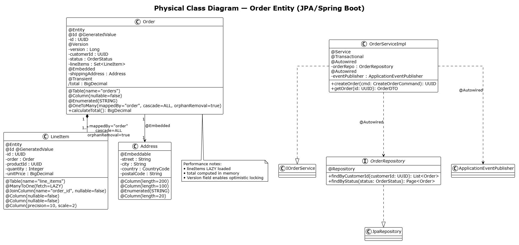
Example: Physical JPA/Spring Implementation
@startuml physical-order-jpa
!theme plain
skinparam linetype ortho
skinparam classAttributeIconSize 0

title Physical Class Diagram — Order Entity (JPA/Spring Boot)

@Entity
@Table(name="orders")
class Order {
    @Id @GeneratedValue
    -id : UUID
    @Version
    -version : Long
    @Column(nullable=false)
    -customerId : UUID
    @Enumerated(STRING)
    -status : OrderStatus
    @OneToMany(mappedBy="order", cascade=ALL, orphanRemoval=true)
    -lineItems : Set<LineItem>
    @Embedded
    -shippingAddress : Address
    @Transient
    /total : BigDecimal
    +calculateTotal(): BigDecimal
}

@Entity
@Table(name="line_items")
class LineItem {
    @Id @GeneratedValue
    -id : UUID
    @ManyToOne(fetch=LAZY)
    @JoinColumn(name="order_id", nullable=false)
    -order : Order
    @Column(nullable=false)
    -productId : UUID
    @Column(nullable=false)
    -quantity : Integer
    @Column(precision=10, scale=2)
    -unitPrice : BigDecimal
}

@Embeddable
class Address {
    @Column(length=200)
    -street : String
    @Column(length=100)
    -city : String
    @Enumerated(STRING)
    -country : CountryCode
    @Column(length=20)
    -postalCode : String
}

@Service
@Transactional
class OrderServiceImpl implements IOrderService {
    @Autowired
    -orderRepo : OrderRepository
    @Autowired
    -eventPublisher : ApplicationEventPublisher
    +createOrder(cmd: CreateOrderCommand): UUID
    +getOrder(id: UUID): OrderDTO
}

@Repository
interface OrderRepository extends JpaRepository<Order, UUID> {
    +findByCustomerId(customerId: UUID): List<Order>
    +findByStatus(status: OrderStatus): Page<Order>
}

Order "1" *-- "1..*" LineItem : mappedBy="order"\ncascade=ALL\norphanRemoval=true
Order "1" --> "1" Address : @Embedded
OrderServiceImpl ..> OrderRepository : @Autowired
OrderServiceImpl ..> ApplicationEventPublisher : @Autowired
OrderRepository ..|> JpaRepository : extends

note bottom of Order
  Performance notes:
  • lineItems LAZY loaded
  • total computed in memory
  • Version field enables optimistic locking
end note
@enduml
Key Observations:
-
JPA annotations define persistence mapping explicitly.
-
Fetch strategies and cascade rules documented on relationships.
-
Spring stereotypes (
@Service,@Repository) mark infrastructure roles. -
Concrete types (
BigDecimal,Set,Page) replace abstractions. -
Repository extends framework interface—technology coupling explicit.
-
Performance-critical decisions (lazy loading, transient fields) annotated.
3. Relationship Semantics: Precision Matters
Misusing relationship types is the most common structural error. Each carries specific lifecycle, ownership, and cardinality semantics.
3.1 Decision Matrix
| Question | Association | Aggregation | Composition |
|---|---|---|---|
| Can the part exist without the whole? | N/A | Yes | No |
| Is ownership exclusive? | No | No | Yes |
| Is lifecycle managed by whole? | No | No | Yes |
| Typical multiplicity at part end | Any | 0..* | 1..* (usually) |
| Example | User borrows Book | Department has Professor | Order contains LineItem |
| Deletion cascade? | Never | Optional | Mandatory |
| Shared references allowed? | Yes | Yes | No |
3.2 Common Misuses and Corrections
❌ Using composition for shared references: Library *-- Book is wrong if books can be borrowed/moved. Use aggregation or association.
✅ Correction: Library o-- Book (aggregation) or Library -- Book (association with role holds).
❌ Using aggregation when lifecycle is bound: Order o-- LineItem is wrong if line items are meaningless without orders.
✅ Correction: Order *-- LineItem (composition).
❌ Omitting multiplicity: Every relationship end must specify cardinality. Default assumptions vary by tool and cause ambiguity.
✅ Correction: Always annotate: 1, 0..1, 0..*, 1..*, n..m.
❌ Bidirectional navigation without justification: Bidirectional associations create tight coupling and serialization cycles.
✅ Correction: Default to unidirectional. Add reverse navigation only when business queries demand it. Document rationale.
❌ Inheritance for code reuse: Using inheritance solely to share attributes/methods violates LSP and creates fragile base classes.
✅ Correction: Prefer composition over inheritance. Extract shared behavior into strategy/visitor/service injected via interface.
4. Mapping Abstraction Levels to Development Lifecycle
| Phase | Primary Diagram | Secondary Diagram | Key Activities |
|---|---|---|---|
| Discovery | Conceptual | — | Domain interviews, ubiquitous language extraction, business rule validation |
| Analysis | Conceptual → Logical | — | Identify bounded contexts, define service boundaries, extract interfaces |
| Design | Logical | Conceptual (reference) | Apply design patterns, define contracts, validate against SOLID |
| Implementation | Physical | Logical (traceability) | Generate code/schemas, configure frameworks, write tests |
| Maintenance | Physical ↔ Logical ↔ Conceptual | All | Refactor with traceability, update business model when domain shifts |
Critical Rule: Never skip the Conceptual level. Teams that jump straight to Logical/Physical produce systems that are technically correct but business-wrong. The Conceptual diagram is your insurance policy against building the wrong thing efficiently.
5. Quality Invariants: The Non-Negotiable Rules
5.1 Structural Integrity
-
Singular Responsibility: Each class maps to exactly one reason to change. If you need “and” to describe its purpose, split it.
-
Liskov Compliance: Subclasses must be substitutable for parents without breaking client code. Test with polymorphic collections.
-
Interface Segregation: No client forced to depend on unused methods. Split fat interfaces into cohesive role-specific ones.
-
Dependency Inversion: High-level modules depend on abstractions, not concretions. Physical diagrams should show this via interfaces, not concrete classes.
-
Explicit Multiplicity: Every association end annotated. No implicit defaults.
-
Navigability Justified: Unidirectional by default. Bidirectional only with documented business query requirement.
5.2 Abstraction Discipline
-
Level Purity: No technology in Conceptual. No business jargon in Physical without glossary link. Logical stays platform-neutral.
-
Traceability Maintained: Every Physical element traces to Logical ancestor. Every Logical element traces to Conceptual ancestor. Gaps indicate missing requirements or gold-plating.
-
Parallel Maintenance: Updates propagate across levels. Version identifiers synchronized. Change logs reference all affected diagrams.
-
Stakeholder Alignment: Conceptual validated by business. Logical reviewed by architects. Physical approved by dev team. Cross-level reviews at integration points.
5.3 Pragmatic Constraints
-
Diagram Size Limit: Max 15-20 classes per diagram. Decompose into subdomains/packages. Use package diagrams for navigation.
-
Attribute/Operation Selectivity: Show only what’s relevant to the diagram’s purpose. Hide getters/setters unless behavioral. Omit inherited members unless overridden.
-
Notes Over Clutter: Use notes for invariants, constraints, and rationale. Don’t encode business rules in attribute names or method signatures.
-
Executable Specifications: PlantUML/YAML/Mermaid preferred over GUI tools. Version-controlled. Diffable. CI-integrated.
-
Living Documentation: Diagrams updated with code. Stale diagrams worse than none. Automate generation from code where possible (reverse engineering), but curate manually for conceptual/logical clarity.
6. Anti-Patterns: Recognizing and Correcting Common Failures
6.1 Anemic Domain Model
Symptom: Classes are pure data holders with only getters/setters. Business logic scattered across services/utilities.
Cause: Procedural thinking disguised as OO; fear of rich domain models; misunderstanding of separation of concerns.
Impact: Loss of encapsulation; duplicated logic; difficult testing; business rules invisible in model.
Correction: Move behavior into domain classes. Services orchestrate, don’t implement. Validate with domain experts: “Would a business person recognize this behavior as belonging to this entity?”
6.2 Premature Physicalization
Symptom: Conceptual diagrams include @Entity, VARCHAR, ForeignKey. Stakeholders confused by technical noise.
Cause: Analysts default to known tech; pressure to “be practical”; lack of abstraction discipline.
Impact: Requirements coupled to stack; re-evaluation impossible; business disengagement.
Correction: Enforce vocabulary bans during conceptual sessions. Review with non-technical stakeholders before proceeding. Maintain separate files per abstraction level.
6.3 Inheritance Abuse
Symptom: Deep hierarchies (>3 levels); subclasses overriding parent behavior inconsistently; base classes with conditional logic based on subtype.
Cause: Code reuse motivation; taxonomic thinking; misunderstanding polymorphism.
Impact: Fragile base class problem; violation of LSP; exponential test complexity.
Correction: Flatten hierarchies. Extract varying behavior into strategies/policies. Favor composition. Apply “Tell, Don’t Ask” principle.
6.4 God Class / Blob
Symptom: Single class with >20 attributes, >30 methods, dependencies on >10 other classes.
Cause: Incremental feature addition without refactoring; lack of cohesion metrics; centralized “manager” anti-pattern.
Impact: Unmaintainable; untestable; blocks parallel development; cognitive overload.
Correction: Apply Extract Class/Method refactorings. Identify cohesive clusters of attributes/methods. Delegate to specialized collaborators. Measure cyclomatic complexity and LCOM4.
6.5 Synchronized Decay
Symptom: Code evolves but diagrams stagnate. New hires learn from outdated models. Audits fail.
Cause: Diagrams treated as deliverables, not living artifacts. No CI integration. Manual update burden.
Impact: Knowledge loss; architectural drift; compliance risk.
Correction: Integrate diagram validation into CI. Auto-generate physical views from code. Require diagram updates in PR checklists. Treat diagrams as first-class source artifacts.
7. Checklist Before You Publish a Class Diagram
Use this gate before treating any Class Diagram as done:
Universal Checks
-
Abstraction level explicitly stated in title/header
-
All classes named with singular nouns
-
All relationships have multiplicity at both ends
-
Role names present on all associations
-
Visibility modifiers specified for all attributes/operations
-
Diagram fits within cognitive limit (<20 classes) or decomposed
-
Notes used for invariants/constraints, not clutter
Level-Specific Checks
Conceptual:
-
Zero technology references
-
Business behaviors modeled, not CRUD
-
Validated by domain expert signature
-
Ubiquitous language consistent with glossary
Logical:
-
Platform-neutral types only
-
Interfaces defined for all service boundaries
-
Design patterns applied intentionally (documented)
-
Traceable to Conceptual model
Physical:
-
Technology annotations complete and accurate
-
Fetch/cascade strategies specified
-
Traceable to Logical model
-
Performance implications documented
Cross-Level Checks
-
Changes propagated across all affected levels
-
Version identifiers synchronized
-
Glossary links maintained between business and technical terms
-
Stakeholder-appropriate audience confirmed for each level
8. Conclusion: The Strategic Value of Disciplined Modeling
A well-constructed Class Diagram is more than documentation—it is an executable specification of architectural intent. By rigorously maintaining the three abstraction levels, enforcing relationship semantics, and applying SOLID invariants, you transform the Class Diagram from a static picture into a dynamic engineering artifact that prevents costly rework, ensures business alignment, and enables sustainable evolution.
The distinction between Conceptual, Logical, and Physical is not academic—it is the primary defense against the two most expensive failures in software projects: building the wrong thing correctly, and building the right thing incorrectly. The Conceptual model ensures you understand the problem. The Logical model ensures you’ve designed a sound solution. The Physical model ensures you can build and operate it reliably.
PlantUML elevates this practice from art to engineering. Text-based, version-controlled, diffable, and CI-integrable, PlantUML diagrams are source code—not decorations. They participate in the same lifecycle as your application code, subject to the same review, testing, and maintenance disciplines.
As you apply these concepts, remember: the ultimate measure of a Class Diagram’s success is not its aesthetic elegance or UML compliance, but its analytical utility. Does it reveal hidden complexities? Does it expose violated invariants? Does it align diverse stakeholders around a shared understanding? Does it survive contact with reality?
Use the checklists as gates. Treat the PlantUML templates as living standards. Maintain traceability ruthlessly. And never forget: the goal is not perfect diagrams, but better software. When executed with discipline, Class Diagram modeling remains one of the most powerful tools for taming complexity and delivering systems that are not only well-built but truly fit for purpose
References
-
From Concept to Code: A Comprehensive UML Class Diagram Guide & Case Study: An extensive guide covering UML class diagram syntax, relationships, and a real-world case study of a food delivery platform .
-
Practical 3: Structural Implementation: A practical session on building a domain model class diagram, including using AI generation and manual refinement in Visual Paradigm .
-
Practical Examples: Building a Simple Class Diagram: A beginner-friendly tutorial that walks through building a simple class diagram for a library management system, defining classes, attributes, and relationships .
-
How to Generate Complex Class Diagrams Using Visual Paradigm’s AI UML Generator: A tutorial focused on using the AI tool to generate complex class diagrams for enterprise applications, with step-by-step instructions and best practices .
-
5.3 Static Structure (Class Diagrams): A guide on automatically deriving class diagrams from use case specifications and sequence diagrams using AI, with practical examples like a dining reservation app .
-
AI Class Diagram Generation: An in-depth article on using the AI Chatbot to generate UML 2.5-compliant class diagrams from natural language descriptions and refining them iteratively .
-
Beginners Guide to Class Diagrams: A fundamental guide (available in multiple languages) that introduces class diagram components and shows how to create them using Visual Paradigm Online .