


Introduction
Business Process Model and Notation (BPMN) has become the universal language for mapping organizational workflows, bridging the critical communication gap between business stakeholders and technical teams. As organizations increasingly demand faster process digitalization, the challenge isn’t just understanding BPMN notation—it’s efficiently transforming complex operational narratives into compliant, executable diagrams.
This guide explores how Visual Paradigm’s comprehensive BPMN 2.0 toolset, enhanced with AI-powered generation capabilities, transforms the traditionally tedious process modeling workflow into an streamlined, intelligent experience. Whether you’re a business analyst documenting your first process or an enterprise architect optimizing multi-departmental workflows, this practical walkthrough demonstrates how to leverage both foundational BPMN principles and cutting-edge automation tools to create professional-grade process models.
Understanding BPMN 2.0 Fundamentals
Business Process Model and Notation (BPMN) is a standardized graphical language maintained by the Object Management Group (OMG) under the latest ISO standard. It provides a universal framework that transforms complex processes into universally understood diagrams. The strength of BPMN lies in its visual consistency—every stakeholder, from C-suite executives to developers, can interpret the same diagram with clarity.
Note: The comprehensive BPMN 2.0 cheat sheet above illustrates all core notation elements, serving as an essential reference for process modelers.
Core Structural Categories
Every effective BPMN diagram relies on five core component classes that work together to capture logic, actors, and data movement. Understanding these categories is essential before diving into tool-specific features.
1. Flow Objects
Flow objects form the backbone of any process diagram:
-
Events: Circular symbols representing occurrences that trigger, interrupt, or end a workflow. These include start events (thin-bordered circles), intermediate events (double-bordered circles for mid-process interruptions), and end events (thick-bordered circles marking termination).
-
Activities: Rounded rectangles indicating specific actions or tasks. These range from simple user tasks (manual actions with person icons) to service tasks (automated scripts with gear icons) and sub-processes (activities with plus signs encapsulating nested workflows).
-
Gateways: Diamond shapes acting as operational decision gates. The exclusive gateway (XOR) forces single-path divergence, the parallel gateway (AND) launches concurrent executions, and the inclusive gateway (OR) directs execution down multiple valid paths.
2. Swimlanes
Swimlanes organize responsibilities and boundaries:
-
Pools: Large containers representing independent organizational entities or distinct processes. Think of pools as separate companies or completely autonomous systems.
-
Lanes: Internal horizontal subdivisions within pools that assign accountability to specific roles or departments. A single pool might contain lanes for “Finance Department,” “Customer Service,” and “Logistics Team.”
3. Connecting Objects
These elements define relationships and flow:
-
Sequence Flow: Solid arrows outlining the exact step-by-step order of operations executed inside a single pool. These never cross pool boundaries.
-
Message Flow: Dashed lines mapping B2B communication and message delivery between separate pools, representing external communications.
-
Associations: Dotted lines linking text comments or physical artifacts to specific flow elements without affecting process logic.
4. Data Elements
Data components track information movement:
-
Data Objects: Icons representing files, data arrays, or physical documents consumed or created during process steps.
-
Data Stores: Symbols designating persistent databases or file architectures where data is archived across sessions.
5. Artifacts
Supplementary elements enhance clarity:
-
Groups: Visual dotted boxes used purely for clustering related task phases without altering flow mechanics.
-
Text Annotations: Contextual side notes attached to shapes to improve reader understanding.
Key Workflow Symbols
While the complete BPMN specification contains dozens of variants, mastering these primary symbols resolves most modeling scenarios:
Events:
-
Start Event: Thin-bordered circle indicating process initiation, potentially containing internal icons like a Clock (Timer trigger) or Envelope (Message receipt)
-
Intermediate Event: Double-bordered circle representing occurrences that interrupt or shift execution paths mid-flight
-
End Event: Thick-bordered circle designating process termination, with filled center variants indicating specific outputs
Activities:
-
User Task: Rounded rectangle with a person icon representing manual actions assisted by software
-
Service Task: Rounded rectangle with mechanical gears designating entirely automated script or web service execution
-
Sub-Process: Activity box featuring a bottom-center plus sign, encapsulating detailed nested process loops
Gateways:
-
Exclusive (XOR): Diamond containing an “X” or left blank, forcing absolute divergence where only one conditional branch can be chosen
-
Parallel (AND): Diamond marked with a plus sign, launching or synchronizing multiple distinct simultaneous forks
-
Inclusive (OR): Diamond containing a circle indicator, directing execution down one, several, or all outgoing paths whose logic conditions are valid
Step-by-Step Modeling Blueprint
Following a structured approach transforms raw operational steps into cleanly validated process models:
Step 1: Define Purpose and Scope
Document explicit starting actions, required end goals, and structural limits of the targeted business workflow. This foundational step prevents scope creep and ensures all stakeholders share the same understanding of process boundaries.
Step 2: Organize Pools and Lanes
Map out participating vendor organizations via individual pools and isolate internal company departments via lanes. This organizational architecture clarifies accountability before a single task is placed.
Step 3: Establish Triggers
Drop the initial Start Event condition to frame what forces the automation or manual workflow to launch. Whether it’s a customer submission, scheduled timer, or received message, the trigger sets the entire process in motion.
Step 4: Sequence Activities and Decisions
Arrange sequential tasks from left to right using clear verb-object syntax, separating optional loops with proper gateways. This chronological flow creates intuitive readability.
Step 5: Refine and Validate
Connect cross-entity gaps using message flows, append relevant data elements, and perform logic checks against compliance constraints. This final polish ensures professional quality.
Modeling Rules & Common Pitfalls
Experienced modelers learn to avoid these critical mistakes:
Never Cross Swimlane Sequence Flows: Solid sequence arrows must never travel between separate pools. Use dashed Message Flows for external communication. This rule maintains clear organizational boundaries.
Balance Every Gateway: Ensure any branching gateway has a matching downstream merging gateway to cleanly unify split structural pathways. Unbalanced gateways create logical inconsistencies.
Always Model Closed Systems: Every independent path must logically terminate at a designated End Event; never leave dangling end tasks. Incomplete paths confuse execution engines and human readers alike.
Standardize Naming Conventions: Keep layouts scannable by naming Activities as Verb + Object (e.g., “Review Invoice”) and Gateways as descriptive questions. Consistent naming accelerates comprehension.
AI-Powered Diagram Generation with Visual Paradigm
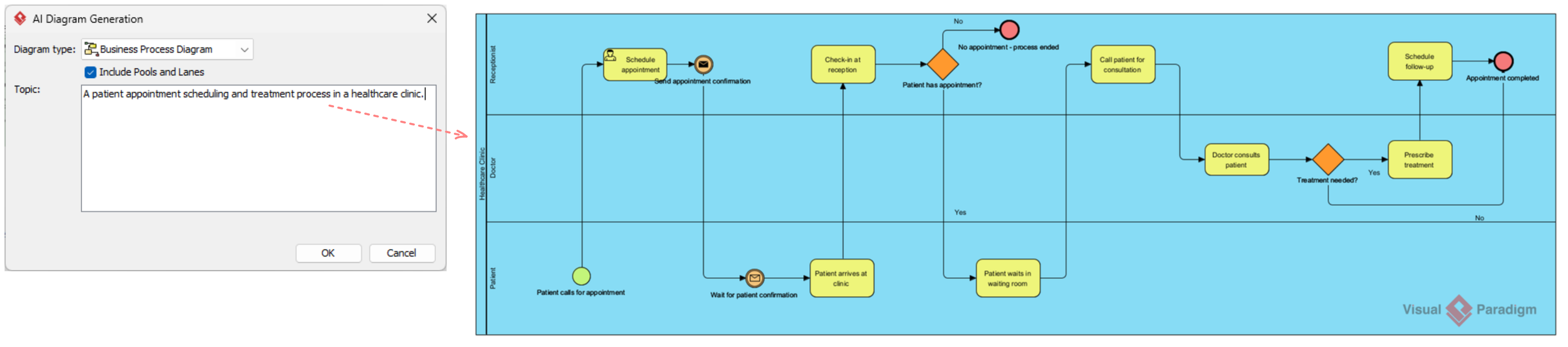
Visual Paradigm integrates an advanced Natural Language Processing (NLP) AI engine directly into its modeling suite, allowing teams to generate interactive, compliant BPMN 2.0 diagrams from textual process narratives. Unlike static visual script generators, Visual Paradigm’s AI acts directly on the modeling database, creating fully draggable, reusable, and synchronized native enterprise elements.
Step-by-Step AI Diagram Generation
The AI generation wizard handles the initial heavy lifting of dragging, dropping, and connecting shapes:
Step 1: Open the Tooling Interface
Launch Visual Paradigm Desktop (Professional Edition or higher). The professional edition provides access to the full AI generation capabilities.
Step 2: Launch the Generator
Navigate to the top application menu bar and click Tools > AI Diagram Generation. This opens the intelligent process modeling interface.
Step 3: Configure the Diagram Settings
In the dialog box configuration settings, choose Business Process Diagram from the drop-down listing. This ensures the AI engine applies BPMN-specific rules.
Step 4: Enforce Structural Architecture
Check the checkbox labeled “Include Pools and Lanes.” This critical setting forces the NLP engine to identify operational actors and automatically map out clean, department-based swimlanes.
Step 5: Submit Your Narrative
Type or paste your procedural workflow description directly into the prompt box and click OK to render native canvas items. The AI instantly generates a complete, editable diagram.
Prompting Strategies for AI-BPMN Generation
Because the engine maps semantic parsing directly to rigid BPMN database definitions, structured inputs yield optimal results over loose conversational scripts.
Ineffective Prompt Example: “Help me design a customer refund process for an e-commerce platform that handles product returns.” This forces too much layout guesswork on structural boundaries.
Effective Prompt Example: “The Customer submits a returns application form. The Customer Service Department reviews the ticket context. If the request is denied, they issue a rejection notification email to the Customer. If approved, the Finance Department processes the bank wire refund while the Logistics Team updates the inventory catalog database.”
Key Prompting Rules
Clearly name explicit actors as proper nouns to force correct Lane placement. Instead of “the department,” use “Customer Service Department” or “Finance Team.”
Use distinct conditional keywords like “If,” “Else,” or “Otherwise” to map data branching down Gateway splits. These trigger words signal decision points.
State sequential steps chronologically to establish clean Sequence Flows. The AI interprets temporal order as process order.
Refining AI Outputs with Core Tooling Features
Once the AI instantiates the foundational model, leverage Visual Paradigm’s native toolset to elevate the diagram from a loose draft into an executable asset.
1. Conversational Refinements via Chatbot
If you spot gaps, you can tweak your composition iteratively using the Visual Paradigm AI Chatbot panel. Issue direct formatting or structural instructions such as:
-
“Add an e-commerce payment gateway to the customer lane.”
-
“Rename the Customer Service Department lane to Support Desk.”
-
“Insert a 3-day Timer Intermediate Event right before the review task.”
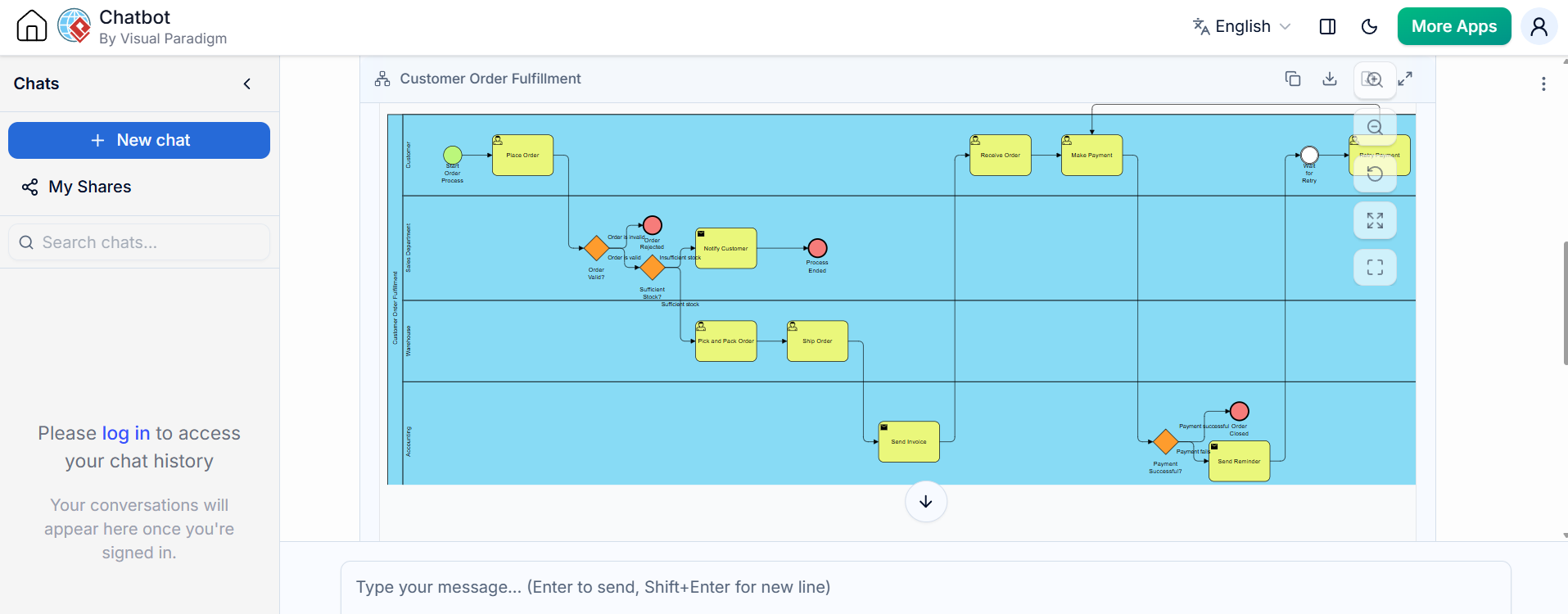
This conversational interface allows rapid adjustments without manual dragging and dropping.
2. Enhancing Logic via the Resource Catalog
To expand paths manually, hover your mouse over an AI-generated task to open the Resource Catalog pointer icon. Click and drag the connector handle outward; the suite intelligently recommends only valid connecting shapes (like specific Gateways or Intermediate Events) to protect against illegal sequence mapping. This context-aware assistance prevents modeling errors.
3. Real-Time BPMN 2.0 Compliance Validation
To verify structural execution integrity, trigger the native BPMN Validation Rules engine. The system scans the active layout to alert you to critical specification compliance issues, catching errors like:
-
Sequence flow arrows illegally jumping across Pool boundaries
-
Orphaned data objects or tasks missing downstream exit connections
-
Diverging exclusive gateways lacking matching convergence endpoints
This automated validation ensures your diagrams meet OMG standards before deployment.
4. Detail Drill-Down (Hierarchical Modeling)
Keep your high-level parent layout highly scannable by clicking a generated task box and transforming it into a formal Sub-Process element. Visual Paradigm allows you to anchor a hyperlinked child canvas beneath the element, hiding granular sub-steps inside a clean, expandable container icon [+]. This hierarchical approach maintains clarity while preserving detail accessibility.

Advanced Tooling Operations
Beyond basic diagram design layouts, Visual Paradigm transforms raw shapes into metrics-driven architectures:
Resource Allocation Matrices: Right-click individual generated activities to bind specific personnel items, operational system tools, or time-to-complete metrics. This connects abstract process flows to concrete resource planning.
Workflow Optimization Simulations: Run active layout loops across customized virtual timelines (minutes, hours, or days) to generate real-time visual Queue Charts, quickly isolating procedural bottlenecks. These simulations reveal performance issues before implementation.
Cost Evaluation Analyses: Input flat currency costs per execution task to have the platform automatically generate an overall cost evaluation overview across nested cycles. This financial perspective supports business case development.
The Visual Paradigm workspace integrates the AI Generator Panel with the BPMN 2.0 Modeling Canvas, creating a seamless environment where text-to-model engines, chatbot refinements, resource catalog paths, and live validation engines work in concert. The BPMN Simulation Engine then adds time scale and cost charts to transform static diagrams into dynamic analytical tools.
Core BPMN Features Supported by Visual Paradigm
Visual Paradigm provides full native support for the global Business Process Model and Notation (BPMN) 2.0 standard, making it a popular tool among business analysts and IT professionals to design, simulate, and analyze workflow processes. It acts as a true semantic modeler rather than a simple drawing tool.
Core BPMN Notation & Modeling Elements
The platform fully implements the official Object Management Group (OMG) BPMN 2.0 specifications:
Swimlanes & Pools: Dedicated horizontal or vertical container layouts clearly segment organizational boundaries, roles, and participants, ensuring visual clarity in complex multi-stakeholder processes.
Flow Objects: Full palette of events (Start, Intermediate, End), Activities (User, Service, Script, Manual tasks), and branching Gateways (Exclusive, Parallel, Inclusive) provides comprehensive modeling capability.
Connecting Objects: Smart management of Sequence Flows within pools and Message Flows crossing pool boundaries maintains logical integrity while supporting inter-organizational communication.
Data & Artifacts: Rich representation of Data Objects, Data Inputs/Outputs, and Text Annotations fully documents data states throughout the workflow, supporting audit and compliance requirements.
Smart Productivity & AI Utilities
AI Text-to-Diagram Generator: Built-in AI interprets natural language descriptions of business procedures and instantly drafts fully interactive, editable BPMN maps with correct swimlanes and logic, dramatically reducing initial modeling time.
Resource Catalog: A quick-access context menu allows you to drag from an existing shape to instantly spawn and connect the next logical element, saving drafting time and preventing notation errors.
Hierarchical Sub-Processes: Supports nesting sophisticated workflows into compact Sub-Process elements that users can smoothly collapse or expand inline to handle complex multi-level workflows without cluttering parent diagrams.
Architecture Integration & Traceability
Model Element Referencing: Easily bind any block or shape to supplemental materials like local files, folders, web URLs, or other internal diagrams to maintain direct traceability between process models and supporting documentation.
Multi-Notation Mapping: Allows you to map process components against other modeling layers, integrating seamlessly with UML shapes, ERD database entities, wireframes, and enterprise architecture models, supporting holistic system design.
Process Performance Statistics: Track metrics directly inside your maps, giving summary reports on process costs, estimated processing hours, and message counts to identify systemic operational bottlenecks and optimization opportunities.
Conclusion
Mastering BPMN 2.0 requires both a solid understanding of standardized notation and access to tools that streamline the modeling process. Visual Paradigm’s comprehensive platform bridges this gap by combining full OMG specification compliance with intelligent automation features that transform how organizations approach process documentation.
The AI-powered diagram generation capability represents a paradigm shift—what once required hours of manual shape placement and connection routing now begins with a well-crafted narrative prompt. However, the true power emerges when combining AI generation with manual refinement, validation tools, and simulation capabilities. This hybrid approach allows teams to rapidly prototype processes while maintaining the precision required for enterprise-grade execution.
For organizations embarking on digital transformation initiatives, the combination of standardized BPMN notation and intelligent tooling provides a scalable foundation for process excellence. Whether documenting simple approval workflows or orchestrating complex multi-system integrations, the principles and techniques outlined in this guide offer a practical roadmap from operational narrative to executable process model. The future of business process modeling lies not in choosing between human expertise and artificial intelligence, but in leveraging both to create clearer, more efficient, and more valuable organizational workflows.
References
-
BPMN for Beginners: A Complete Guide to Business Process Modeling Notation: Comprehensive introduction to BPMN fundamentals and modeling best practices
-
Process Design Tool: Overview of Visual Paradigm’s process design capabilities and features
-
BPMN Made Easy: Simplified approach to creating BPMN diagrams with intelligent tooling
-
Visual Paradigm Tutorial Video: Video demonstration of BPMN modeling techniques and workflows
-
Project Management Learning Resources: Educational materials on process modeling within project management contexts
-
What is BPMN: Explanation of BPMN concepts and diagramming fundamentals
-
BPMN Guide: Complete guide to Business Process Model and Notation standards
-
BPMN Tutorial: Step-by-step BPMN tutorial covering core notation elements
-
BPMN Activity Types Explained: Detailed breakdown of different activity types in BPMN
-
Comprehensive Guide to BPMN: In-depth exploration of BPMN concepts, benefits, and practical applications
-
Sequence and Message Flows: Technical documentation on connecting objects in BPMN
-
BPMN Tutorial Part 3: Advanced BPMN modeling techniques and examples
-
Data Objects in BPMN: Guide to modeling data elements and artifacts
-
BPMN Tutorial Part 1: Introduction to BPMN diagram creation and basic elements
-
From Narrative to Diagram: How AI BPMN generator transforms process modeling workflows
-
BPMN Diagram and Tools: Feature overview of BPMN diagramming tools and capabilities
-
Visual Paradigm Features: Complete list of Visual Paradigm features and functionalities
-
Drawing Business Process Diagrams: User guide for creating business process diagrams
