


Software architecture demands more than just functional correctness. It requires a foundation that withstands growth, change, and complexity. At the heart of this structural integrity lies the Unified Modeling Language (UML) Composite Structure Diagram. This specific diagram type allows architects to visualize the internal arrangement of classifiers and their interactions. When applied strategically, these diagrams become blueprints for systems that expand without collapsing.
Scalability is not merely about handling more data; it is about managing structural complexity. By decomposing complex systems into manageable parts, teams can ensure that every component serves a defined purpose. This guide explores the mechanics of Composite Structure Diagrams, focusing on how to leverage their features for long-term maintainability and flexibility.
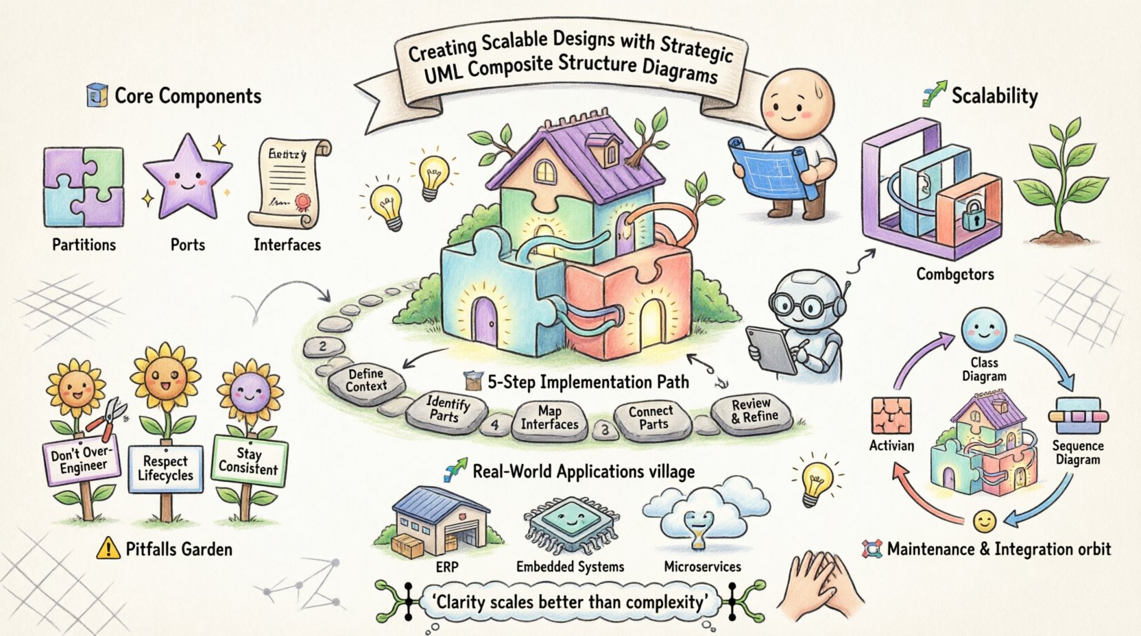
Understanding the Core Components 🧩
A Composite Structure Diagram reveals the internal structure of a classifier. Unlike Class Diagrams that show relationships between classes, this diagram digs deeper into the anatomy of a single class. It displays how parts are assembled and how they communicate.
1. Partitions and Ports
At the top level of this diagram are partitions. These represent the internal parts of the classifier. Each partition encapsulates a specific responsibility. Within these partitions, you define ports. Ports are interaction points where a part exposes its services.
- Partitions: Define the structural boundaries of internal components.
- Ports: Act as interfaces for communication between parts or with the external environment.
- Interfaces: Define the contract a port must satisfy.
By separating internal logic from external interaction, you create a modular design. This separation is critical when scaling. If one part needs to change, the external contracts remain stable, provided the port interface does not break.
2. Internal Connectors
Connectors link ports together. They represent the flow of data or control within the system. In a scalable design, connectors should be explicit. Hidden dependencies are the enemy of maintainability.
When drawing internal connectors, consider the following:
- Ensure every connection has a clear source and target.
- Label connectors with the type of data passing through.
- Use named connectors to reference them in documentation.
Explicit connectivity reduces the cognitive load on developers. When troubleshooting, the path of execution is visible in the diagram.
Structuring for Scalability 📈
Scalability in design means the ability to grow without redesigning the core. Composite Structure Diagrams support this by allowing nested structures. You can define a part that is itself a composite structure. This recursion allows for hierarchical modeling.
1. Aggregation vs. Composition
Understanding the lifecycle of parts is essential. The relationship between the whole and its parts determines scalability.
| Relationship Type | Lifecycle Dependency | Use Case |
|---|---|---|
| Composition | Strong | Parts cannot exist without the whole (e.g., Engine in Car). |
| Aggregation | Weak | Parts can exist independently (e.g., Department in University). |
Choosing the correct relationship affects how you scale. Composition ensures strict boundaries. Aggregation allows for more flexibility and reuse.
2. Nested Structures
Complex systems often require multiple layers of abstraction. A Composite Structure Diagram can nest composite structures within other composite structures. This feature mirrors the reality of microservices or modular monoliths.
- Define a high-level container.
- Insert a sub-structure as a part.
- Expose the sub-structure’s ports via the parent’s ports.
This technique hides complexity. The outer layer interacts with the sub-structure through a simplified interface. This is vital for large-scale enterprise systems where teams work on different modules simultaneously.
Strategic Implementation Steps 🛠️
Creating these diagrams requires a disciplined approach. Rushing leads to cluttered diagrams that obscure rather than clarify. Follow a structured process to ensure quality.
Step 1: Define the Context
Before drawing, identify the classifier being modeled. What is the “whole”? What is the responsibility of this specific class? Ensure the scope is defined clearly.
Step 2: Identify Internal Parts
List the components that make up the classifier. Are they other classes? Are they interfaces? Group them logically. Each group should represent a cohesive unit of functionality.
Step 3: Map Interfaces
For each part, determine what it needs to receive and what it must provide. Define the ports accordingly. Use standard interfaces where possible to encourage compatibility.
Step 4: Connect the Parts
Draw the internal connectors. Ensure data flows logically. Avoid cross-connections that create tight coupling. If a part needs access to another part’s data, route it through the appropriate ports.
Step 5: Review and Refine
Check for consistency. Does the diagram match the Class Diagram? Does it align with the Sequence Diagram? Consistency across views prevents confusion during implementation.
Common Pitfalls and How to Avoid Them ⚠️
Even experienced architects make mistakes. Recognizing common traps helps maintain design integrity.
1. Over-Engineering
Not every class needs a Composite Structure Diagram. Use them when internal complexity is high. For simple classes, a Class Diagram suffices. Creating diagrams for every entity adds maintenance overhead.
2. Ignoring Lifecycle
As mentioned earlier, the lifecycle of parts matters. If you treat a part as a composition when it should be an aggregation, you limit reusability. Review the relationship constraints during the design phase.
3. Inconsistent Naming
Names must be consistent across all UML diagrams. If a port is named “getData” in the Composite diagram, it should be named “getData” in the Sequence diagram. Inconsistency breaks the mental model of the system.
Maintaining Diagrams Over Time 🔄
A diagram that is not updated becomes a liability. In a scalable architecture, changes are frequent. The diagrams must evolve alongside the code.
- Version Control: Treat diagrams as code. Store them in version control systems.
- Change Management: When code changes, update the diagram. Do not rely on memory.
- Automated Validation: If possible, use tools that validate diagram consistency against the codebase.
Maintainability is a continuous process. It requires commitment from the entire team. Documentation is not a one-time task; it is a living part of the development lifecycle.
Integration with Other UML Diagrams 🔄
Composite Structure Diagrams do not exist in isolation. They interact with other modeling tools to provide a complete picture of the system.
1. Class Diagrams
Class Diagrams show the static structure of the system. Composite Structure Diagrams show the internal structure of specific classes. They complement each other. Use Class Diagrams for the macro view and Composite Structure Diagrams for the micro view.
2. Sequence Diagrams
Sequence Diagrams show the flow of messages over time. Composite Structure Diagrams show where those messages originate and terminate. When a Sequence Diagram references a part, the Composite Structure Diagram defines that part’s internal capabilities.
3. Activity Diagrams
Activity Diagrams model the flow of control. They can reference composite structures to show which internal component handles a specific activity. This linkage ensures that the logical flow matches the physical structure.
Best Practices for Team Collaboration 🤝
Large projects involve many developers. A shared understanding of the architecture is crucial. Composite Structure Diagrams facilitate this understanding.
- Standardize Templates: Define a standard way to draw these diagrams. Use consistent colors and line styles.
- Define Guidelines: Create a style guide for ports and connectors. Specify naming conventions.
- Review Sessions: Include diagram reviews in the code review process. Ensure the design matches the implementation.
Collaboration reduces risk. When everyone understands the internal structure, they can contribute without breaking dependencies.
Real-World Application Scenarios 🌍
Where do these diagrams shine? They are particularly useful in complex domains.
1. Enterprise Resource Planning (ERP)
ERP systems are massive. They contain many interconnected modules. Composite Structure Diagrams help isolate the logic of specific modules like Inventory or Accounting. This isolation makes it easier to update one module without affecting others.
2. Embedded Systems
Embedded systems often have strict memory and processing constraints. Modeling the internal structure helps optimize resource allocation. You can see exactly which hardware components interact with which software parts.
3. Microservices Architecture
Even in distributed systems, individual services have internal structures. Using these diagrams to model a single service helps ensure that the service remains maintainable as it grows.
Advanced Techniques for Complex Systems 🔬
For highly complex systems, standard modeling might not be enough. Consider advanced techniques.
1. Parameterized Classes
Use parameterized classes to define generic structures. This allows you to model a pattern once and apply it multiple times. It reduces duplication and ensures consistency.
2. Constraint Specifications
Add constraints to your diagram. Specify limits on the number of parts or the types of connections allowed. This adds a layer of validation to your design.
3. Behavioral Integration
Combine structural diagrams with behavioral models. Show how state changes affect the internal structure. This provides a dynamic view of the system’s evolution.
Conclusion and Final Thoughts 🧠
Building scalable software is a strategic endeavor. It requires careful planning and clear communication. UML Composite Structure Diagrams provide the necessary framework for this work. By focusing on parts, ports, and connectors, architects can create systems that are robust and adaptable.
Remember that the goal is clarity. A diagram should simplify complexity, not add to it. Use these tools to make the internal workings of your system visible to the team. This visibility fosters better decision-making and reduces the risk of technical debt.
As you implement these practices, focus on consistency and maintenance. A well-documented architecture is an asset that pays dividends over the lifetime of the project. Prioritize the structural integrity of your design, and the scalability will follow naturally.

