


Understanding the internal architecture of a system requires more than just knowing what classes exist. It requires seeing how those classes interact internally, how they expose services, and how they connect to the outside world. The UML Composite Structure Diagram provides this deep level of visibility. It is a specialized structural diagram that models the internal composition of a classifier, revealing the parts that make up a whole, the roles they play, and the connections between them.
This guide explores the anatomy of the Composite Structure Diagram in detail. We will examine every element, from parts and ports to interfaces and connectors, ensuring you understand how to construct clear, effective models for complex software systems.
1. Why Use a Composite Structure Diagram? 📊
Standard class diagrams show relationships between classes, but they often fail to depict the internal organization of a complex class. When a class contains multiple components that collaborate to perform a function, a composite structure diagram becomes essential. It helps architects visualize:
- The internal parts of a class or object.
- The interfaces exposed by those parts.
- The connections (connectors) between internal parts.
- The delegation of responsibilities between the classifier and its parts.
By breaking down a complex unit into manageable pieces, teams can better understand dependencies, manage complexity, and ensure that internal changes do not break external contracts.
2. The Core Components of the Diagram 🔍
A composite structure diagram is built upon a specific set of elements. Each has a distinct meaning and notation. Below is a breakdown of the primary building blocks.
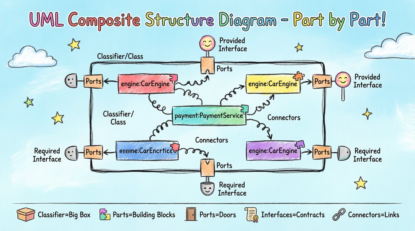
2.1. The Classifier or Class Node 🏗️
The outer boundary of the diagram represents the classifier being modeled. This is typically a class, interface, or component. It acts as the container for all internal parts. In the visual representation, this is the large rectangle that encompasses the entire diagram. It defines the scope of the composite structure.
- Classifier: The entity whose internal structure is being described.
- Boundaries: The outer box defines the extent of the composite structure.
2.2. Parts (The Building Blocks) 🧱
Parts are the internal instances of other classifiers that reside within the composite structure. They are the actual objects or components that make up the whole. A part is essentially a reference to a specific instance of a class within the context of the composite.
- Notation: A small rectangle labeled with the part name and type (e.g., engine: CarEngine).
- Multiplicity: You can specify how many instances of a part exist (e.g., 1..*).
- Role: Sometimes a part is defined by the role it plays rather than just its type.
2.3. Ports (Interaction Points) 🚦
Ports define the interaction points between the composite structure and its environment, or between parts within the structure. They are the gateways through which services are requested or provided. A port encapsulates the interaction logic, hiding internal details.
- Provided Interface: A service offered by the part or port to the outside.
- Required Interface: A service needed by the part or port from the outside.
- Notation: A small rectangle attached to the boundary of a part or the classifier itself.
2.4. Interfaces (Contracts) 📜
Interfaces define the set of operations that can be performed. In a composite structure diagram, interfaces are often shown as small circles or lollipop notation attached to ports. They specify the contract without revealing the implementation.
- Provided Interface (Lollipop): Indicates functionality the part offers.
- Required Interface (Socket): Indicates functionality the part needs.
2.5. Connectors (Links) 🔗
Connectors represent the physical or logical links between ports. They show how data or control flows between different parts of the composite structure or between the structure and external systems.
- Internal Connectors: Link ports within the same classifier.
- External Connectors: Link ports to the outside environment.
- Notation: A solid line connecting two ports.
3. Visualizing Relationships and Structure 📐
The arrangement of these elements creates a map of the system’s internal logic. Here is a summary table of the key elements and their visual representations.
| Element | Visual Notation | Purpose |
|---|---|---|
| Classifier | Large Rectangle | Container for the internal structure |
| Part | Small Rectangle inside | Instance of a class within the composite |
| Port | Small Rectangle on boundary | Interaction point for communication |
| Provided Interface | Circle (Lollipop) | Service offered to the environment |
| Required Interface | Semicircle (Socket) | Service needed from the environment |
| Connector | Solid Line | Link between ports |
4. Understanding Roles and Multiplicity 🔄
Roles and multiplicity add precision to the definition of parts. They clarify how many instances of a part exist and what specific job that instance performs within the system.
4.1. Role Names
A role name describes the function a part serves. For example, in a car system, a Car class might have a part of type Engine. The role name could be mainEngine or backupEngine. This distinguishes multiple instances of the same type.
- Clarity: Helps developers understand the specific responsibility of each part.
- Flexibility: Allows the same class type to be used in different contexts within the same structure.
4.2. Multiplicity Constraints
Multiplicity defines the number of instances allowed. This is crucial for understanding resource allocation and system capacity.
- 1: Exactly one instance.
- 0..1: Zero or one instance (optional).
- 1..*: One or more instances (at least one).
- 0..*: Zero or more instances (optional collection).
5. Internal vs. External Interaction 🌐
One of the most powerful features of the Composite Structure Diagram is the distinction between internal and external interactions. This separation helps in managing complexity.
5.1. Internal Interactions
These occur between parts within the same classifier. They are typically not visible to the outside world. Internal connectors link the ports of internal parts.
- Encapsulation: Keeps internal logic hidden.
- Delegation: The classifier delegates work to its parts.
5.2. External Interactions
These occur between the classifier and the rest of the system. They are exposed through the ports on the boundary of the classifier.
- API Definition: Defines the public contract.
- Integration: Shows how the system fits into the larger architecture.
6. Practical Examples 🛠️
To truly grasp the anatomy, let us look at a practical scenario involving a software architecture for an e-commerce platform.
6.1. The Order Processing System
Consider a class named OrderProcessor. This class manages the lifecycle of a customer order. Its internal structure might include:
- Part 1: PaymentGateway (Type: PaymentService, Role: securePayment).
- Part 2: InventoryManager (Type: StockService, Role: stockCheck).
- Part 3: NotificationService (Type: EmailService, Role: customerUpdate).
The OrderProcessor exposes a port that requires a PaymentInterface. It provides a OrderManagementInterface to the outside. Internally, the PaymentGateway connects to the OrderProcessor port for payment confirmation. The InventoryManager connects to verify stock before payment is finalized.
6.2. Benefits of This Model
- Decoupling: The OrderProcessor does not need to know the internal details of the PaymentGateway, only its interface.
- Swappability: If a different payment provider is needed, the internal part can change without affecting the external contract.
- Clarity: Developers can see exactly which services are required for an order to complete.
7. Comparison with Class Diagrams 📊
It is common to confuse Composite Structure Diagrams with standard Class Diagrams. While they share similarities, their focus differs significantly.
| Feature | Class Diagram | Composite Structure Diagram |
|---|---|---|
| Focus | Relationships between classes | Internal structure of a single class |
| Granularity | High level, abstract | Low level, concrete instances |
| Parts | Attributes and Associations | Explicit Part Instances |
| Ports | Not typically used | Central to interaction definition |
| Use Case | General system design | Component integration and delegation |
8. Best Practices for Modeling 🚀
Creating effective diagrams requires adherence to certain principles to ensure they remain useful over time.
- Keep It Readable: Avoid overcrowding. If a class has too many internal parts, consider splitting the diagram.
- Consistent Naming: Use clear, consistent names for parts, ports, and interfaces.
- Minimize Complexity: Do not model every single method. Focus on structural composition and major interactions.
- Document Roles: Always specify the role name for parts if multiple instances of the same type exist.
- Validate Interfaces: Ensure that provided interfaces match the actual operations implemented by the parts.
9. Common Pitfalls to Avoid ⚠️
Even experienced modelers can make mistakes when using this diagram type. Being aware of common errors helps maintain accuracy.
- Over-Modeling: Trying to show every attribute inside the composite structure. Focus on parts and interactions.
- Confusing Ports with Attributes: Ports are for communication; attributes are for data storage. Do not mix them.
- Ignoring Multiplicity: Failing to specify how many parts exist can lead to ambiguity in implementation.
- Disconnected Ports: Every port should have a clear connection to another port or an interface. Unconnected ports suggest incomplete logic.
- Static vs. Dynamic: Remember this is a structural diagram. It does not show the sequence of events, only the potential for interaction.
10. Implementation Considerations 💻
When translating these diagrams into code, the mapping is direct but requires discipline.
- Composition: In object-oriented languages, parts are often implemented as member variables or private fields.
- Ports: These can be realized through interfaces or abstract base classes.
- Connectors: These are realized through method calls or dependency injection.
- Encapsulation: The diagram enforces encapsulation. Code should reflect the private nature of internal parts.
11. Advanced Scenarios 🚀
As systems grow, the composite structure diagram evolves to handle more complex requirements.
11.1. Nested Structures
A part can itself be a composite structure. This allows for hierarchical modeling. You can nest a composite structure diagram inside another part definition. This is useful for complex subsystems.
- Benefit: Allows for drill-down modeling.
- Caution: Can become very deep. Use with care.
11.2. Generic Parts
Parts can be generic, meaning they can be instantiated with different types. This is common in templated software architectures.
- Flexibility: One structure can support multiple data types.
- Reusability: Reduces the need for multiple similar diagrams.
12. Summary of Key Takeaways 📝
The UML Composite Structure Diagram is a vital tool for software architects. It provides a granular view of how a system is built from the inside out. By understanding the anatomy of parts, ports, roles, and connectors, teams can design systems that are modular, maintainable, and clear.
Key points to remember include:
- Parts represent internal instances of classifiers.
- Ports define interaction points for services.
- Connectors link ports to establish communication paths.
- Interfaces define the contracts for provided and required services.
- Multiplicity defines the quantity of parts involved.
By applying these concepts consistently, you can create models that serve as accurate blueprints for development. This clarity reduces errors during implementation and facilitates better collaboration among stakeholders.
13. Final Thoughts on Structural Modeling 🧠
Structural modeling is not just about drawing boxes and lines. It is about thinking clearly about how components fit together. The Composite Structure Diagram forces this discipline. It requires you to define exactly what goes inside a class and how it talks to the rest of the world.
When used correctly, this diagram reduces ambiguity. It answers the question of “how” a class works internally, rather than just “what” it does. This distinction is crucial for large-scale enterprise systems where internal complexity can easily spiral out of control.
Invest time in learning this diagram type. The effort pays off in cleaner code and more robust architectures. Start by modeling simple components and gradually increase the complexity as your understanding grows.

