


In software architecture, understanding the external behavior of a component is often not enough. To truly grasp how a system functions, developers must look inward. The UML Composite Structure Diagram provides a mechanism to visualize the internal organization of a classifier. This diagram type exposes the parts, roles, and connections that make up the inside of a complex class or component.
Unlike standard class diagrams that focus on relationships between classes, the Composite Structure Diagram focuses on the internal composition of a single unit. It answers the question: “What makes this thing work?” This guide explores the mechanics, syntax, and practical applications of this essential modeling tool.
🔍 What is a Composite Structure Diagram?
A Composite Structure Diagram is a type of Unified Modeling Language (UML) diagram. It displays the internal structure of a classifier. In object-oriented design, a classifier can be a class, interface, or component. This diagram breaks that classifier down into its constituent parts.
- Classifier: The main entity being analyzed (e.g., a specific class like
MediaPlayer). - Internal Structure: The arrangement of parts that form the classifier.
- Collaboration: How these parts interact to fulfill the responsibilities of the classifier.
When a class becomes too complex to understand through a simple attribute and method list, a composite structure diagram offers clarity. It shows how smaller units collaborate to form a larger whole. This is particularly useful for modeling design patterns like the Composite Pattern or Bridge Pattern.
🧩 Core Elements of the Diagram
To read and create these diagrams effectively, one must understand the specific notation used. The diagram relies on four primary concepts: Parts, Ports, Connectors, and Roles. Each plays a distinct function in defining the internal topology.
1. Parts 🧱
A part represents an instance of a classifier that exists within the boundary of the composite structure. It is essentially a field or member variable, but with a focus on structural connection rather than just data storage.
- Notation: A rectangle with a small triangle attached to the left side, or a nested rectangle.
- Labeling: The name of the part usually appears above the type of the part.
- Example: A
MediaPlayerclass might have a part namedaudioPlayerof typeAudioEngine.
2. Ports 🌐
Ports define interaction points on the boundary of the internal structure. They act as the interface through which the internal parts communicate with the outside world or with other parts inside the structure. Ports encapsulate the complexity of internal implementation.
- Function: They specify where services can be provided or required.
- Types: They can be input ports, output ports, or bidirectional ports.
- Benefit: They allow for decoupling. The internal logic can change without affecting external interactions as long as the port contract remains the same.
3. Connectors 🔗
Connectors link parts to each other or link parts to ports. They represent the flow of data or control between components.
- Internal Connectors: Join two parts within the same classifier.
- External Connectors: Join a part to a port on the boundary.
- Interface Implementation: Connectors often show how a part implements an interface provided by a port.
4. Roles 🎭
Roles describe the perspective from which a part is viewed within a relationship. A single part might play multiple roles in different contexts. A role is often represented as a small circle (ball) at the end of a connector.
- Provided Role: The part offers a service to the outside.
- Required Role: The part needs a service from the outside.
- Clarity: Roles help clarify which specific responsibilities a part fulfills in a larger interaction.
📐 Syntax and Visual Notation
Visual consistency is key to effective modeling. The Composite Structure Diagram uses specific shapes to convey meaning quickly.
| Element | Visual Representation | Meaning |
|---|---|---|
| Classifier | Rectangle with a folded corner or compartmentalized box | The main object being modeled |
| Part | Rectangle inside the classifier boundary | A constituent component |
| Port | Small square or rectangle on the boundary | Interaction point |
| Connector | Line connecting parts or ports | Relationship or data flow |
| Role | Small circle attached to the end of a connector | Function of the connection |
🆚 Composite Structure vs. Class Diagrams
Many developers confuse Composite Structure Diagrams with standard Class Diagrams. While both deal with classes, their scope and purpose differ significantly. Understanding when to use which is critical for effective documentation.
- Class Diagram Scope: Focuses on relationships between multiple classes (inheritance, association, aggregation). It is a static view of the system’s architecture.
- Composite Structure Scope: Focuses on the internal makeup of a single class. It is a detailed view of a specific unit’s anatomy.
Consider the following comparison:
| Feature | Class Diagram | Composite Structure Diagram |
|---|---|---|
| Primary Focus | Inter-class relationships | Intra-class composition |
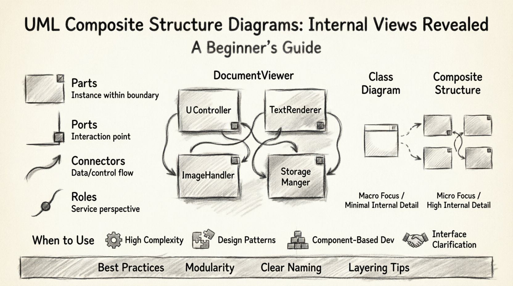
| Granularity | Macro (System level) | Micro (Component level) |
| Internal Detail | Minimal (Attributes/Methods) | High (Parts/Ports/Connectors) |
| Best Used For | Overview of system structure | Designing complex internal logic |
🛠️ Practical Application Example
Let us examine a concrete scenario to see how these concepts apply in a real-world context. Imagine a DocumentViewer application.
Scenario: Document Viewer Architecture
The DocumentViewer is a complex system. It needs to render text, handle images, and manage user input. A simple class diagram would show DocumentViewer as a black box with methods like render() and save(). A Composite Structure Diagram reveals the engine behind the scenes.
Internal Composition
- Part 1:
TextRenderer - Role: Provides the service of displaying text characters.
- Connection: Connected to an input port named
textStream. - Part 2:
ImageHandler - Role: Manages the loading and scaling of image data.
- Connection: Connected to an input port named
imageStream. - Part 3:
UIController - Role: Coordinates the actions between renderer and handler.
- Part 4:
StorageManager - Role: Handles reading from disk and writing changes.
Interaction Flow
The UIController acts as the central hub. It receives a request to open a file via the openFile port. It directs the StorageManager to fetch data. Once data is retrieved, the UIController routes text data to the TextRenderer and image data to the ImageHandler. Finally, the rendered content is sent to the screen via an output port.
This level of detail allows architects to see potential bottlenecks. If the ImageHandler is slow, the UIController can be designed to buffer requests, preventing the entire viewer from freezing.
🚀 When to Use This Diagram
Not every class requires a composite structure diagram. Over-documentation can lead to maintenance nightmares. Use this diagram when specific conditions are met.
- High Complexity: The class contains many nested objects or dependencies.
- Design Patterns: You are implementing patterns like Composite, Facade, or Bridge that rely on internal structure.
- Component-Based Development: You are designing systems where parts are swapped out or reused across different contexts.
- Interface Clarification: You need to show how internal parts implement specific interfaces.
If a class is simple with only a few attributes and methods, a standard class diagram suffices. Save the Composite Structure Diagram for the heavy lifters of your architecture.
🧪 Design Patterns and Modeling
The Composite Structure Diagram is particularly powerful when modeling recursive structures. This is common in file systems, GUI toolkits, and organizational charts.
The Composite Pattern
In the Composite Pattern, clients treat individual objects and compositions of objects uniformly. The diagram helps visualize this recursion.
- Leaf Component: A part that has no children.
- Composite Component: A part that can contain other parts.
- Visualizing Recursion: The diagram shows how a
Containerpart holds a list ofItemparts. TheItempart can itself be aContainer.
The Facade Pattern
A Facade provides a simplified interface to a complex subsystem. The diagram shows how the Facade part hides the internal complexity of the subsystem parts from the external client.
- Front Door: The Facade port.
- Back End: The subsystem parts connected internally.
- Encapsulation: Clients do not see the subsystem parts directly.
⚠️ Common Pitfalls and Best Practices
Creating these diagrams requires discipline. Avoid common mistakes that reduce their utility.
Pitfalls
- Over-Engineering: Modeling every single internal variable. Focus on structural relationships, not data attributes.
- Inconsistency: Mixing internal and external views confusingly. Keep the boundary clear.
- Ignoring Ports: Forgetting to define ports leads to unclear interaction points. Always define how parts talk to the outside.
- Static vs. Dynamic: Remember that this diagram is structural. It does not show the sequence of operations. Use Sequence Diagrams for flow.
Best Practices
- Modularity: Keep the number of parts manageable. If a structure has too many parts, consider splitting the classifier.
- Clear Naming: Name ports and connectors based on the service they provide or require (e.g.,
readAccess,writeAccess). - Layering: If the internal structure is deep, consider nesting composite structures or using multiple diagrams for different views.
- Documentation: Add notes to explain complex interactions that cannot be shown visually.
🔗 Integration with Other UML Diagrams
A Composite Structure Diagram does not exist in isolation. It integrates with the broader UML suite to provide a complete picture of the system.
- Class Diagram: The Composite Structure Diagram is a refinement of a class definition in a Class Diagram. You can link them to show that the detailed view belongs to the class.
- Component Diagram: If a classifier is a component, the Composite Structure Diagram details its internal logic, while the Component Diagram details how it connects to other components.
- Sequence Diagram: While the Composite diagram shows structure, the Sequence diagram shows how those parts interact over time. Use both for a full understanding.
- Deployment Diagram: Once the internal structure is defined, you can decide which parts need to run on separate machines or processes.
📝 Implementation Considerations
When moving from design to code, the Composite Structure Diagram serves as a blueprint. It informs how developers instantiate classes and manage dependencies.
- Dependency Injection: Parts often represent dependencies that should be injected rather than hardcoded.
- Interface Segregation: Ports encourage the creation of small, focused interfaces rather than large, monolithic ones.
- Testing: The clear definition of parts and ports makes unit testing easier. You can mock ports to test specific parts in isolation.
- Refactoring: If the internal structure needs to change, the diagram highlights what interfaces (ports) must remain stable to prevent breaking external clients.
🧭 Conclusion on Internal Modeling
The UML Composite Structure Diagram is a specialized tool for deep architectural analysis. It moves beyond the surface of what a class does to explain how it is built. By defining parts, ports, and connectors, teams gain a shared understanding of complex internal logic.
While it adds a layer of detail that might seem unnecessary for simple projects, its value becomes apparent in large-scale systems. It promotes decoupling, clarifies responsibilities, and supports the implementation of robust design patterns. Use it when the internal view matters more than the external interface.
Start applying these concepts to your next complex class. Map out the parts. Define the ports. Connect the roles. You will find that the internal complexity of your software becomes much easier to manage and explain.

