


As software systems evolve, the internal architecture becomes increasingly intricate. Developers and architects often face the challenge of visualizing how individual components interact within a single classifier. While class diagrams provide a high-level view of relationships, they frequently lack the granularity needed to describe the internal composition of a system. This is where the UML Composite Structure Diagram becomes an essential tool. It offers a detailed perspective on the internal structure of classifiers, revealing the parts, roles, and connections that drive functionality.
Understanding this specific diagram type is crucial for anyone involved in system modeling. It bridges the gap between abstract design and concrete implementation. By mapping out the internal boundaries and interfaces, teams can ensure that dependencies are managed correctly. This guide explores the mechanics, applications, and best practices for utilizing composite structure diagrams effectively.
What is a Composite Structure Diagram? 🤔
A Composite Structure Diagram is a specialized type of UML diagram. It focuses on the internal structure of a classifier. Unlike a standard class diagram that shows attributes and operations, this diagram visualizes the parts that make up a class and how they collaborate. It answers the question: What constitutes this object, and how do its pieces communicate?
The diagram highlights the following aspects:
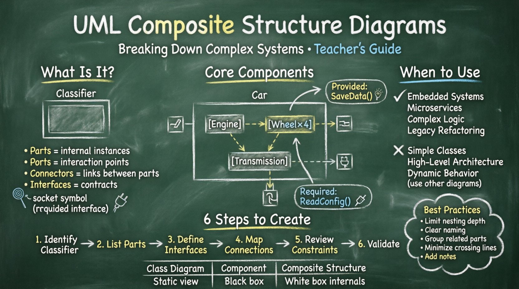
- Parts: The instances of classes that exist within the composite.
- Ports: Points of interaction where parts connect to the outside world.
- Connectors: The physical or logical links between parts.
- Interfaces: The contracts that define how parts interact.
This level of detail is particularly useful in complex domains like embedded systems, microservices, or large-scale enterprise applications. It prevents the “black box” syndrome where a component is treated as an indivisible unit without understanding its internal mechanics.
Core Components of the Diagram 🧩
To construct a meaningful composite structure diagram, one must understand the specific building blocks available. Each element serves a distinct purpose in defining the system’s topology.
1. Parts and Roles
Parts represent the instances of other classifiers that reside within the composite. For example, a Car class might contain parts like Engine, Wheel, and Transmission. Each part has a role that defines its behavior within the composite context.
- Instance Specification: Defines a specific part within the structure.
- Role: A label indicating how the part behaves in relation to the composite.
- Multiplicity: Specifies how many instances of a part exist (e.g., 1 Engine, 4 Wheels).
2. Ports
Ports act as the boundaries for interaction. They define the entry and exit points for communication. A port is essential for encapsulation, ensuring that internal parts do not expose themselves directly to the outside environment.
- Provided Interface: The functionality the part offers to others.
- Required Interface: The functionality the part needs from others.
3. Connectors
Connectors establish the relationships between ports and parts. They represent the flow of data or control signals. In a composite structure diagram, connectors are vital for showing how the internal parts collaborate to achieve the composite’s purpose.
- Physical Links: Represent hardware connections or network cables.
- Logical Links: Represent method calls or data passing.
4. Interaction Constraints
Sometimes, the interaction between parts is governed by specific rules. Interaction constraints define the conditions under which a connection is valid. This adds a layer of logic to the structural definition.
Interfaces in Composite Structures 🔌
Interfaces play a central role in this diagram type. They decouple the implementation from the usage. By defining standard interfaces, the internal parts can be swapped without affecting the overall system, provided they adhere to the interface contract.
Provided vs. Required Interfaces
Understanding the direction of dependency is key. A part may provide a service (like a Database Connection) or require a service (like a Logger).
| Interface Type | Definition | Visual Symbol | Example |
|---|---|---|---|
| Provided | Functionality offered by the part | Full Circle (Lollipop) | SaveData() |
| Required | Functionality needed by the part | Half Circle (Socket) | ReadConfig() |
Connecting a required interface to a provided interface creates a valid interaction path. This visual representation helps identify missing dependencies early in the design phase.
When to Use Composite Structure Diagrams 📊
Not every system requires this level of detail. Using these diagrams indiscriminately can lead to unnecessary complexity. It is best reserved for scenarios where internal composition is critical.
Appropriate Use Cases
- Embedded Systems: Where hardware components interact with software modules.
- Microservices: Defining the internal API contracts of a service.
- Complex Business Logic: When a single class contains multiple collaborating sub-objects.
- Legacy Refactoring: Understanding how old components are wired together before modification.
When to Avoid
- Simple Classes: A class with only attributes and methods does not need this diagram.
- High-Level Architecture: Use Component or Deployment diagrams for broader views.
- Dynamic Behavior: Use Sequence or State diagrams for runtime behavior.
Steps to Create an Effective Diagram 🛠️
Creating a clear diagram requires a systematic approach. Following a structured process ensures consistency and readability.
- Identify the Classifier: Determine which class or component requires internal visualization.
- List Internal Parts: Break down the classifier into its constituent parts.
- Define Interfaces: Specify what each part provides and requires.
- Map Connections: Draw connectors between ports to show communication paths.
- Review Constraints: Add any interaction constraints or rules.
- Validate: Check for orphaned ports or disconnected parts.
During this process, maintain a focus on clarity. Avoid nesting too deeply. If a part itself is complex, consider creating a separate diagram for it rather than exploding the current view.
Comparison with Other Diagram Types 🆚
Confusion often arises between Composite Structure, Class, and Component diagrams. Understanding the distinctions helps in selecting the right tool for the job.
| Diagram Type | Focus | Internal Detail | Best Used For |
|---|---|---|---|
| Class Diagram | Attributes, Operations, Relationships | Low (Shows Associations) | Static Structure |
| Component Diagram | Large Scale Modules | Medium (Black Box) | System Architecture |
| Composite Structure | Internal Parts & Ports | High (White Box) | Internal Composition |
While a class diagram shows that Class A has an instance of Class B, a composite structure diagram shows how that instance connects via ports and interfaces. It moves beyond static association to functional connectivity.
Best Practices for Clarity 🎯
Readability is the primary goal of any diagram. If the diagram cannot be understood at a glance, it fails its purpose.
1. Limit Nesting Depth
Deeply nested structures are difficult to parse. If a part contains another composite structure, consider using a separate diagram for the inner structure. This keeps the current view manageable.
2. Consistent Naming Conventions
Use clear names for parts, ports, and roles. Avoid abbreviations that are not standard. A part named db_conn is less clear than DatabaseConnection.
3. Group Related Parts
Use frames or nested rectangles to group parts that belong to a logical subsystem. This visual grouping aids in understanding the organization.
4. Minimize Cross-Connections
Long lines crossing the diagram create visual noise. Arrange parts so that connections are as short and direct as possible. Use layers or zones if necessary.
5. Document Constraints
Do not rely solely on visual lines. Add notes or constraints where the logic is non-obvious. This provides context for the reader.
Common Pitfalls to Avoid ⚠️
Even experienced modelers can fall into traps when creating these diagrams. Being aware of common mistakes helps maintain quality.
- Over-Engineering: Modeling every single attribute as a part. Only model parts that have distinct behavior or lifecycle.
- Ignoring Ports: Connecting parts directly without ports. This violates encapsulation principles.
- Missing Interfaces: Forgetting to define what functionality is exposed. This leads to integration issues later.
- Inconsistent Abstraction: Mixing high-level concepts with low-level implementation details in the same view.
- Static Only: Failing to account for dynamic instantiation of parts. Some parts are created at runtime, which a static diagram cannot fully capture.
Impact on System Maintenance 🔄
The value of this diagram extends beyond the design phase. It serves as a living document for maintenance and debugging.
Debugging
When a system fails, the composite structure diagram helps trace the path of data. If a component returns an error, the diagram shows which port and interface were involved. This speeds up root cause analysis.
Refactoring
When changing internal implementations, the diagram ensures that external contracts remain intact. It highlights dependencies that might break if a part is replaced.
Documentation
New team members often struggle with complex systems. A composite structure diagram provides a clear map of the internal landscape. It reduces the learning curve for onboarding.
Integrating with Other Models 🔗
No diagram exists in isolation. The composite structure diagram should align with the broader system model.
- Class Diagrams: Ensure the parts in the composite structure correspond to classes defined in the class diagram.
- Sequence Diagrams: Use the ports and interfaces defined here to set up interactions in sequence diagrams.
- Deployment Diagrams: Map the parts to physical nodes if the system is distributed.
This alignment ensures consistency across the documentation set. Discrepancies between diagrams often indicate gaps in understanding or design flaws.
Advanced Considerations 🚀
For very large systems, standard diagrams may become unwieldy. Advanced modeling techniques can help manage this complexity.
Sub-Frames
Use sub-frames to isolate specific subsystems within a larger composite. This allows for a “zoom-in” capability without cluttering the main view.
Parameterized Types
Generic parts can be modeled using parameterized classifiers. This allows for reusable structures where the specific type is defined at instantiation.
Behavioral Notes
Adding behavioral constraints to parts can clarify how they react to events. This adds a layer of dynamic context to the static structure.
Conclusion on System Modeling 📝
Effective modeling is about clarity, not complexity. The UML Composite Structure Diagram provides a powerful lens for examining the internal composition of systems. By defining parts, ports, and interfaces explicitly, teams gain visibility into the mechanics of their software.
Adopting this diagram type requires discipline. It demands careful consideration of what to include and what to abstract. However, the payoff is a more robust architecture and better communication among stakeholders. When used correctly, it simplifies the understanding of complex systems without sacrificing necessary detail.
Focus on the interactions that matter. Keep the diagram aligned with the code. Use it as a reference for development and maintenance. In doing so, the internal structure of the system becomes as clear as the external interface.

