


In the complex landscape of software architecture, visualizing the internal workings of a system is as critical as defining its external behavior. The UML Composite Structure Diagram offers a unique window into this internal world. Unlike class diagrams that focus on static relationships, or sequence diagrams that focus on dynamic flows, the composite structure diagram reveals how parts interact within a whole. This guide explores the mechanics of ports and connectors, the essential building blocks of this diagram type.
When architects design systems, they often face the challenge of managing complexity. High-level abstractions can hide critical implementation details. Ports and connectors bridge this gap. They define the specific points where a component accepts or provides functionality. By mastering this notation, teams can create clearer specifications that reduce ambiguity during development.
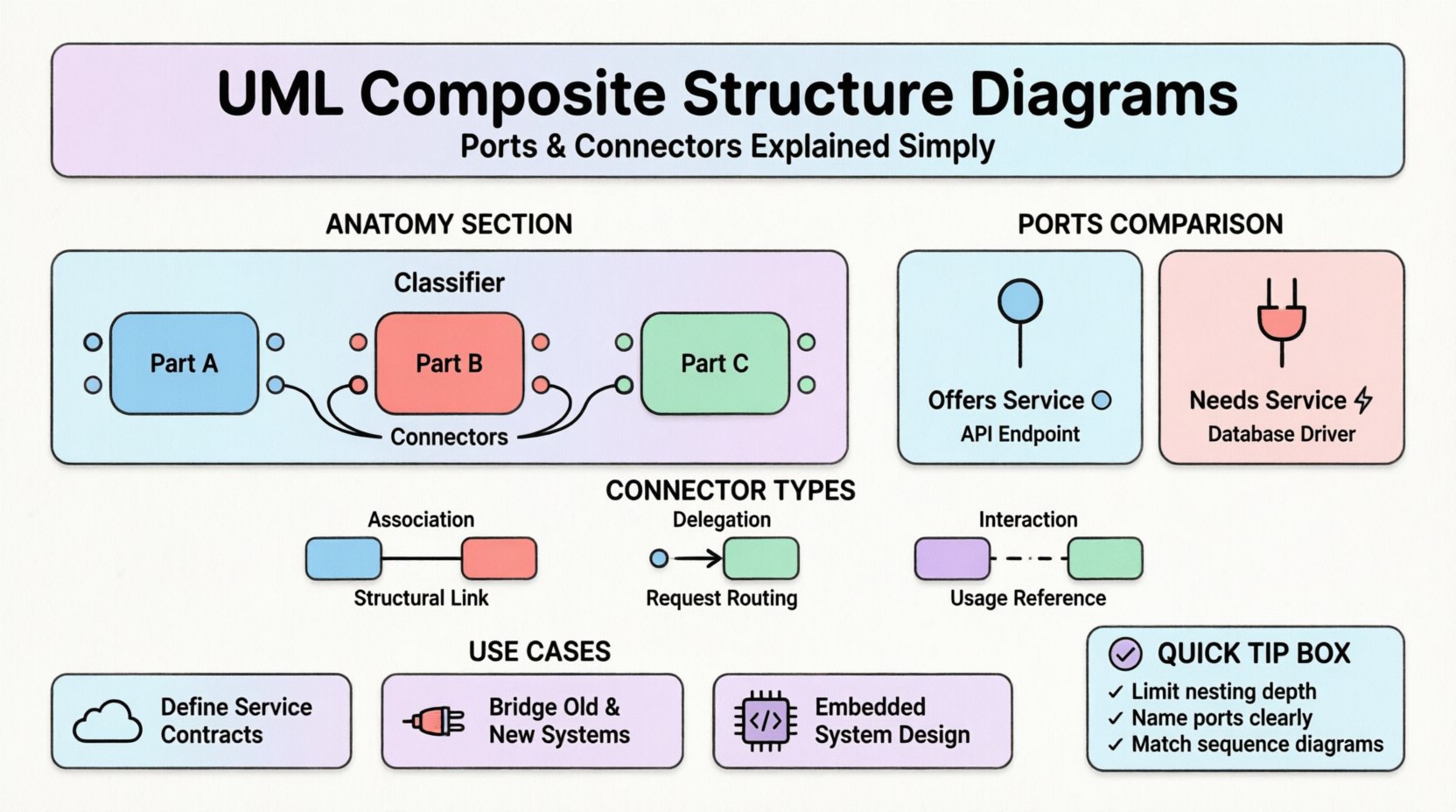
🧩 The Anatomy of a Composite Structure
A composite structure diagram represents the internal structure of a classifier. It shows how parts are assembled to form a complex whole. The fundamental elements involved are the classifier itself, its parts, and the interactions between them.
- Classifier: The top-level entity being decomposed. This could be a class, component, or subsystem.
- Parts: The internal components that make up the classifier. Each part has a specific type and role.
- Ports: Interaction points that define how a part communicates with the outside world or other parts.
- Connectors: Links that establish communication channels between ports.
Visualizing these elements allows developers to see the boundaries of responsibility. It clarifies which part handles data processing, which handles user input, and how they exchange information without tight coupling.
⚡ Understanding Ports: The Interaction Points
Ports are perhaps the most distinct feature of the composite structure diagram. They serve as the interface between the internal world of a classifier and its environment. Without ports, a classifier would have no defined way to connect to other elements. A port encapsulates the interaction points, ensuring that internal changes do not break external connections.
Provided vs. Required Interfaces
Ports are categorized based on the direction of the interaction. This distinction is vital for understanding dependency and flow.
- Provided Interface: A port that offers functionality to the outside. It is often visualized with a “lollipop” notation. The component “provides” a service.
- Required Interface: A port that needs functionality from the outside. It is often visualized with a “socket” or “plug” notation. The component “requires” a service.
Consider a payment processing module. It might require a validation service to check card details and provide a transaction confirmation service to the user interface. A composite structure diagram clearly separates these two needs.
| Feature | Provided Port | Required Port |
|---|---|---|
| Notation | Lollipop (🔘) | Socket (⚡) |
| Direction | Outbound (Serving) | Inbound (Consume) |
| Dependency | Others depend on this | This depends on others |
| Example | API Endpoint | Database Driver |
🔗 Connectors: Establishing Communication
Once ports are defined, they need a way to talk. Connectors provide this pathway. They link the ports of different parts or link a part to the external environment. A connector defines the nature of the communication, ensuring that data flows correctly between components.
Types of Connectors
Not all connections are the same. The diagram distinguishes between different types of links based on their function.
- Association Connector: Represents a structural link. It implies a relationship that persists over time, such as ownership or composition.
- Delegation Connector: A specialized connector that passes requests from the outside of a classifier directly to an internal part. This hides the internal complexity.
- Interaction Usage: Defines how a part uses a specific interaction defined elsewhere.
Delegation connectors are particularly powerful. They allow a composite structure to present a simplified interface to the outside while routing specific calls to internal sub-components. For example, a “User Manager” part might delegate “Password Reset” requests to an internal “Auth Service” part, without the external caller knowing the internal split.
🏗️ Visual Notation and Syntax
Clarity in modeling depends on consistent notation. While tools may vary slightly, the UML standard provides specific guidelines for drawing these diagrams.
- Part Box: A rectangle representing the internal part. It often includes the name and type.
- Port Box: A small rectangle attached to the part boundary. It is labeled with the interface name.
- Connector Line: A solid line connecting two ports. It may have arrows indicating directionality in some notations.
- Role Name: Labels on the connector indicating the specific role played at that end of the connection.
When drawing these diagrams, consistency is key. If you use a specific icon for a required interface in one diagram, use it in all related diagrams. This reduces cognitive load for the reader.
🔍 Practical Application Scenarios
Understanding the theory is one thing; applying it is another. Here are common scenarios where composite structure diagrams add value.
1. Microservices Architecture
In distributed systems, services must communicate via defined APIs. A composite structure diagram can model a single service, showing its internal logic and how it exposes ports for other services. This helps in defining contract boundaries before code is written.
2. Legacy System Integration
When integrating old systems with new ones, adapters are often needed. The diagram can show an adapter component with specific required ports (for the old system) and provided ports (for the new system). This visualizes the translation layer.
3. Hardware-Software Co-Design
In embedded systems, software runs on hardware. A composite structure diagram can show the CPU as a part, with ports representing memory buses or interrupt lines. This bridges the gap between electrical engineering and software engineering.
📊 Comparison with Other UML Diagrams
It is easy to confuse composite structure diagrams with other structural diagrams. Knowing when to use which prevents redundancy and confusion.
- Class Diagram: Focuses on attributes and methods of classes. It does not show internal composition of a single class as clearly as the composite structure diagram.
- Component Diagram: Focuses on deployable units. It is less granular than the composite structure diagram, which can show internal logic.
- Deployment Diagram: Focuses on physical hardware nodes. It does not show logical internal structure.
| Diagram Type | Primary Focus | Best Used For |
|---|---|---|
| Composite Structure | Internal Parts & Ports | Complex Class Composition |
| Class Diagram | Attributes & Methods | Code Structure |
| Component Diagram | Deployable Units | System Modules |
| Sequence Diagram | Message Flow | Behavioral Logic |
🛡️ Best Practices for Modeling
To ensure these diagrams remain useful over time, follow these guidelines.
- Limit Depth: Avoid nesting composite structures too deeply. If a part has its own internal structure that is complex, consider making it a separate diagram.
- Clear Naming: Use meaningful names for ports. “Input” is vague. “Data Ingestion Port” is clear.
- Interface Separation: Keep interfaces abstract. Do not couple the port directly to a concrete class unless necessary. This allows the internal implementation to change without breaking the contract.
- Consistency with Sequence Diagrams: Ensure the ports defined here match the interactions shown in sequence diagrams. If a sequence diagram shows a message on a port, that port must exist in the composite structure.
🚫 Common Pitfalls to Avoid
Even experienced modelers make mistakes. Being aware of common errors helps maintain diagram integrity.
- Over-Modeling: Trying to show every single method call in a composite structure diagram. This clutters the view. Focus on structural boundaries, not behavioral details.
- Missing Delegation: Forgetting to show how external requests reach internal parts. This makes the diagram misleading regarding data flow.
- Incorrect Multiplicity: Not specifying how many instances of a part exist. A part can be mandatory (1), optional (0..1), or multiple (0..*). This affects memory and lifecycle management.
- Ignoring Interfaces: Connecting ports directly to parts without defining the interface they implement. This leads to tight coupling in the design.
🔄 Integration with Behavioral Diagrams
Structure and behavior are two sides of the same coin. A composite structure diagram gains more meaning when paired with behavioral diagrams.
- State Machine Diagrams: Parts can have internal states. The composite structure shows where these states live. A state change in one part might trigger a port interaction.
- Activity Diagrams: These can show the flow of work between parts. The composite structure defines the “who” (the parts), while the activity diagram defines the “how” (the process).
- Interaction Diagrams: These validate the connectors. If a connector is drawn, there should be a message sequence that utilizes it.
🎓 Conclusion on Structural Modeling
Designing robust systems requires more than just writing code. It requires a clear mental model of how components fit together. The UML Composite Structure Diagram provides that model through ports and connectors. It allows architects to define boundaries, manage dependencies, and visualize internal complexity.
By adhering to the principles of clear notation and proper interface separation, teams can reduce errors and improve collaboration. These diagrams serve as a contract between design and implementation. They ensure that when the code is written, the internal structure matches the architectural intent. This alignment is the foundation of maintainable, scalable software.
As you continue to model systems, consider using these diagrams to document complex classes. They offer a level of detail that class diagrams cannot match. With practice, the notation becomes second nature, allowing you to focus on the logic of the system rather than the syntax of the diagram.

