


Designing complex software systems requires more than just listing classes and their methods. It demands a clear understanding of how components fit together, how they interact, and how internal structures are organized. The UML Composite Structure Diagram provides a specialized view for modeling these internal compositions. This guide explores the mechanics of nested parts and interfaces, offering a structured approach to system architecture.
Modern applications often consist of multiple layers of abstraction. A single class rarely operates in isolation. Instead, it collaborates with other entities to fulfill a specific role. The Composite Structure Diagram captures this reality by showing the internal structure of a classifier. It breaks down the system into parts, ports, and interfaces, allowing architects to visualize the relationships that drive functionality. This level of detail is crucial for maintaining scalability and ensuring that dependencies are managed effectively.
🧩 Understanding the Core Elements
Before constructing a diagram, one must understand the building blocks. The diagram relies on specific notations that define the behavior and structure of the system. The following elements form the foundation of this modeling technique.
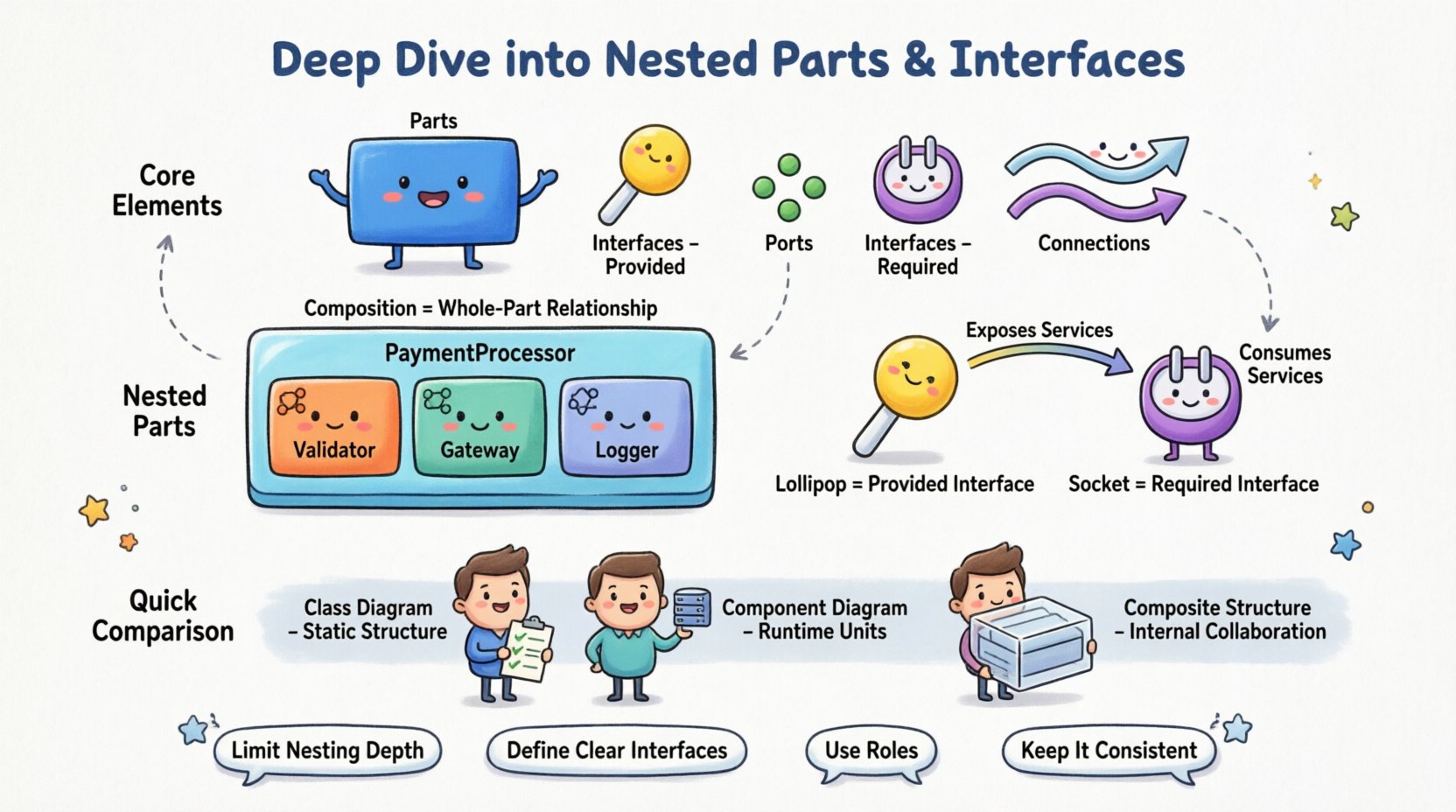
- Parts: A part represents a structural element within a classifier. It is an instance of a classifier that exists as a component of a larger whole. Parts can be simple objects or complex structures themselves.
- Interfaces: Interfaces define a set of operations that a part must provide or require. They act as contracts, decoupling the implementation from the usage. An interface specifies what a part can do, without revealing how it does it.
- Ports: A port is a designated interaction point for a part. It defines where connections to other parts occur. Ports encapsulate the interface, ensuring that interactions happen through a controlled boundary.
- Connections: Lines that link parts to ports or interfaces. They represent the flow of data or control between components.
Visualizing these elements correctly is essential. A part is typically drawn as a rectangle placed inside the boundary of the classifier. The interface is often depicted as a circle (lollipop) for provided interfaces or a socket for required interfaces. This visual distinction helps stakeholders quickly identify dependencies and capabilities.
🔗 The Power of Nested Parts
Nesting allows for the representation of internal hierarchies within a single classifier. Instead of treating a part as a black box, nesting reveals its internal composition. This is particularly useful for complex subsystems where one component contains several sub-components.
📦 Composition and Aggregation
When defining nested parts, the relationship between the whole and the parts is critical. The diagram distinguishes between different types of composition.
- Composition: A strong form of association where the part cannot exist independently of the whole. If the whole is destroyed, the part is also destroyed. This is often depicted with a filled diamond on the whole side of the connection.
- Aggregation: A weaker form of association where the part can exist independently. If the whole is destroyed, the part may continue to exist. This is depicted with an empty diamond.
Consider a scenario involving a PaymentProcessor class. This class might not just handle transactions directly. It could contain nested parts such as a Validator, a Gateway, and a Logger. By nesting these parts within the PaymentProcessor structure, the diagram explicitly shows that the processor is built from these specific units. This aids in understanding the lifecycle management of each unit.
🏗️ Structural Hierarchy
Nesting creates a hierarchy that mirrors the code structure. If a class contains other objects as member variables, the composite structure diagram reflects this ownership. This is valuable for:
- Identifying lifecycle dependencies.
- Clarifying ownership and responsibility.
- Visualizing complexity without cluttering the top-level view.
Without nesting, a system might appear as a flat list of classes. With nesting, the relationships become a tree structure. This makes it easier to trace how a change in a deep-level part affects the parent classifier. It also helps in identifying high coupling within the internal structure.
🔌 Managing Interfaces and Roles
Interfaces are the glue that holds the system together. They define the points of interaction between parts. In a composite structure diagram, interfaces are not just abstract concepts; they are concrete connection points.
🔌 Provided vs. Required Interfaces
Understanding the direction of dependency is key to a well-designed system.
- Provided Interface: This interface represents a service that the part offers to the outside world. It is often drawn as a “lollipop” symbol. Any part inside the composite can connect to this interface to expose functionality.
- Required Interface: This interface represents a service that the part needs from the outside world. It is often drawn as a “socket” symbol. The part cannot function without these services being supplied by another part.
| Interface Type | Symbol | Function | Dependency Direction |
|---|---|---|---|
| Provided | Lollipop (Circle) | Exposes services | Outgoing |
| Required | Socket (U-shape) | Consumes services | Incoming |
This distinction helps in analyzing the system’s modularity. A part that requires many interfaces is dependent on others, while a part that provides many interfaces is a potential hub of functionality. Balancing these roles ensures that no single part becomes a bottleneck or a point of excessive coupling.
🔄 Role Assignment
A single part can play multiple roles simultaneously. For example, a DataStore part might be required as a Writer by one interface and provided as a Reader by another. This flexibility allows the same internal component to serve different needs within the composite structure. It reduces redundancy and promotes reuse.
When modeling this, label the interface end of the association with the specific role name. This clarifies the context in which the part is being used. It prevents ambiguity regarding which interface satisfies which requirement.
🛠️ Designing for Collaboration
The ultimate goal of the composite structure diagram is to show how parts collaborate to achieve system goals. It shifts the focus from individual behavior to interaction.
🔗 Internal Connections
Connections between parts are internal to the classifier. They represent the wiring that makes the system work. These connections link a required interface on one part to a provided interface on another part within the same composite.
- Direct Connections: A direct line between two ports.
- Connector Roles: A connector may have roles that specify how data flows through it. This adds detail to the interaction model.
Internal connections should be minimized where possible to reduce coupling. If two parts need to communicate, they should do so through a well-defined interface. Direct links can lead to tight coupling, making the system harder to maintain.
🚪 External Boundaries
Parts exposed to the outside world are critical. The diagram should clearly show which interfaces are accessible from outside the composite. This defines the public API of the classifier.
- Interfaces on the boundary of the composite are accessible.
- Interfaces internal to the composite are hidden.
This encapsulation is vital for information hiding. It allows the internal structure to change without affecting external clients, as long as the boundary interfaces remain stable.
📊 Comparison with Other Diagrams
It is important to understand where the Composite Structure Diagram fits within the broader UML suite. It is not a replacement for other diagrams but a complement.
| Diagram Type | Focus | Best Used For |
|---|---|---|
| Class Diagram | Attributes, Methods, Relationships | Static structure and data modeling |
| Component Diagram | Large-scale deployment, files, binaries | System architecture and deployment |
| Composite Structure Diagram | Internal structure, nesting, ports | Complex object composition and interaction |
While a Class Diagram shows that a Car has an Engine, a Composite Structure Diagram shows how the Engine is connected to the Car‘s electrical system via specific ports. It reveals the mechanism of connection, not just the existence of a link.
🚦 Best Practices for Implementation
Creating these diagrams requires discipline. Over-complicating the structure can lead to confusion. Adhering to best practices ensures clarity and utility.
- Limit Nesting Depth: Deep nesting can obscure relationships. Keep the hierarchy to two or three levels for readability.
- Define Clear Interfaces: Avoid generic interfaces. Specify exactly what operations are provided or required.
- Use Roles: Always label the ends of connectors with role names to indicate the context of the interaction.
- Keep it Consistent: Use standard notation for ports and interfaces. Deviations can confuse readers.
- Focus on Structure: Do not include behavioral details like state transitions. Keep the focus on structural relationships.
When mapping this model to code, the structure should guide the class design. Ports translate to interfaces in the code. Parts translate to private member variables. Connections translate to dependency injection or method calls.
🔍 Common Pitfalls and Solutions
Even experienced designers can make mistakes when using this diagram type. Recognizing common issues helps in avoiding them.
🚫 Ambiguous Connections
If a connection does not have a clear interface, it is ambiguous. Ensure every connection links a required interface to a provided interface. Do not connect parts directly without an interface unless modeling a direct internal dependency.
🚫 Over-Abstraction
Using too many layers of interfaces can make the diagram hard to read. If a part only has one interface, consider if the interface is necessary. Sometimes, a direct port is sufficient for internal communication.
🚫 Ignoring Lifecycle
Nested parts often have specific lifecycles. Ensure the diagram reflects whether parts are created with the whole or instantiated independently. This affects resource management and memory allocation strategies.
🌐 Real-World Application Scenarios
These diagrams are not just theoretical. They solve real problems in system design.
- Microservices Architecture: A microservice can be modeled as a composite structure showing its internal dependencies on databases, caches, and external APIs.
- Plugin Systems: A core application can be modeled to show how it accepts plugins through specific interfaces, allowing for dynamic extension.
- Embedded Systems: Hardware components often have strict interfaces. Modeling these ensures that software interacts correctly with the physical hardware.
In each case, the diagram provides a blueprint for implementation. It reduces the risk of integration errors by defining the contract before code is written.
📝 Summary of Key Takeaways
The UML Composite Structure Diagram is a powerful tool for detailing the internal organization of a system. It moves beyond simple class relationships to show composition, nesting, and interaction points.
- Parts represent the structural building blocks inside a classifier.
- Interfaces define the contracts for interaction, distinguishing between provided and required services.
- Ports act as the specific connection points for these interfaces.
- Nesting allows for hierarchical modeling of complex components.
By utilizing these elements effectively, architects can create designs that are robust, maintainable, and clear. The diagram bridges the gap between abstract requirements and concrete implementation. It ensures that the structural integrity of the system is maintained throughout the development lifecycle.
When designing complex systems, taking the time to model the composite structure pays dividends. It reveals hidden dependencies and clarifies responsibilities. This clarity leads to better code, fewer bugs, and a system that is easier to evolve over time.
Focus on the relationships, respect the boundaries, and use the interfaces to decouple your components. This approach forms the basis of a resilient software architecture.

