


Structural modeling in software engineering requires precision. When defining the internal architecture of a class, the UML Composite Structure Diagram (CSD) provides the necessary granularity. However, practitioners often encounter significant hurdles when constructing these diagrams. Errors in notation, semantic misinterpretation, and confusion regarding containment versus association can render a diagram useless for documentation or code generation.
This guide addresses the specific technical challenges associated with UML Composite Structure Diagrams. It offers a deep dive into common pitfalls, syntax violations, and semantic ambiguities. By understanding the mechanics of Parts, Ports, Connectors, and Nodes, you can resolve structural inconsistencies effectively.
🏗️ Understanding the Foundation of Composite Structures
Before troubleshooting, one must revisit the core components. A Composite Structure Diagram depicts the internal structure of a classifier. It shows how parts are assembled to form the whole. The confusion often arises from treating these internal components the same as standard class attributes or associations.
Key elements include:
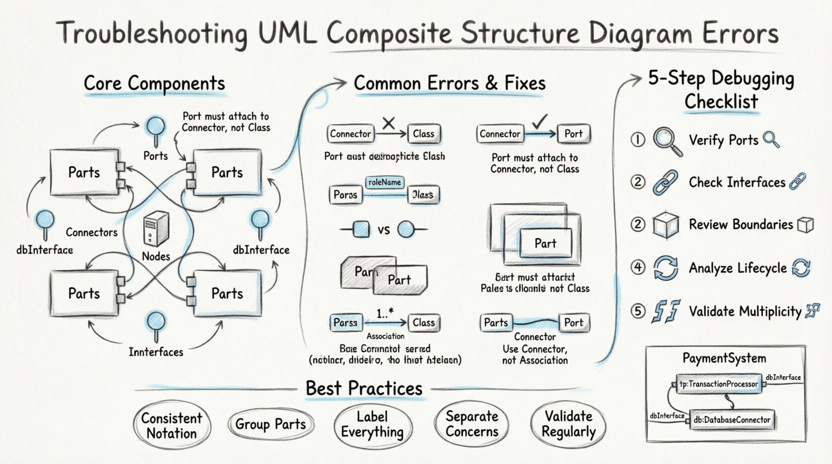
- Parts: Instances of a classifier that exist within the composite structure. They represent the composition relationship.
- Ports: Interaction points where parts expose their capabilities to the outside world or to other internal parts.
- Connectors: Links that establish communication paths between ports.
- Nodes: Physical or computational hardware that hosts the software parts.
- Interfaces: Contracts defined by ports that specify the operations available.
Many errors stem from conflating these elements. For instance, using a standard association line where a connector is required, or labeling a part without defining its role. Clarity in these definitions prevents downstream confusion during implementation.
🧩 Syntax Errors in Parts and Roles
Syntax errors are the most visible issues. They occur when the diagram violates the standard notation rules defined by the UML specification. These errors often prevent diagram rendering tools from processing the model correctly.
1. Incorrect Part Naming and Stereotypes
Every part must have a clear name. If the part represents a specific instance of a class, the name should reflect that instance. Often, users omit the colon separator between the part name and the type.
- Correct:
engine:Motor - Incorrect:
engine Motor
Additionally, omitting stereotypes when necessary can lead to ambiguity. If a part represents a specific hardware component, using the stereotype <<hardware>> clarifies its nature. Without this, the diagram looks like standard software composition.
2. Missing Role Names
When a part connects to another via a role, the role name is mandatory. A role defines the perspective from which the part is viewed. A common error is connecting two parts without defining the role on the connector end.
If Part A connects to Part B, and Part A expects a specific interface, the role name must be stated. For example, if a Controller part connects to a Display part, the Controller end might be labeled controllerInterface. Missing this creates ambiguity about which service is being consumed.
3. Improper Nesting of Internal Structures
Sometimes, developers attempt to nest composite structures within other composite structures without proper boundaries. While valid, this creates visual clutter. If a part contains another composite structure, the inner structure must be clearly delineated. A common error is drawing the border of the inner composite overlapping with the outer part boundary.
🔌 Connector and Port Misconfigurations
The communication pathways within a composite structure are defined by connectors. These are distinct from associations because they represent physical or logical links between interaction points (ports), not just between classes.
1. Port-Connector Mismatch
A connector must link ports. It cannot link a port to a class directly, nor can it link two classes directly without ports. A frequent error is drawing a line between a part and a class, expecting it to function as a connector.
- Rule: Connectors only connect ports.
- Rule: Ports must be explicitly defined on the part.
If a connector is drawn to a part directly, the diagram is technically invalid. The connection must terminate on the specific port symbol, usually a small square on the boundary of the part.
2. Interface Realization Errors
Ports can specify required interfaces or provided interfaces. A required interface means the part needs to consume a service. A provided interface means the part offers a service. Confusing these leads to logic errors in the system design.
For example, if a UserInterface part needs to send data, it has a required interface. If a DataServer part sends data, it has a provided interface. A connector should link the required interface of the client to the provided interface of the server. Swapping these results in a diagram that implies the server is asking for data from the client, which is incorrect.
3. Connector Multiplicity
Connectors can have multiplicities, just like associations. However, the placement of multiplicity on a connector is often misinterpreted. Multiplicity should be placed near the end of the connector line, indicating how many instances of the target part can connect.
Common mistake: Placing multiplicity on the part itself rather than the connector end. While related, the connector multiplicity specifies the relationship capacity, not the instance count of the part.
🔄 Semantic Confusion: Containment vs. Association
This is the most common source of conceptual error. Users often confuse the composition relationship (containment) with a standard association.
1. The Life Cycle Rule
In a composite structure, the lifecycle of the parts is typically tied to the lifecycle of the composite. If the composite structure is destroyed, its parts are destroyed. This is a stronger relationship than aggregation or association.
When drawing the internal structure, the lines connecting parts are typically solid lines, indicating composition. If you use a hollow diamond or a standard line, you change the semantic meaning of the relationship.
- Composition: Strong ownership. Parts cannot exist without the composite.
- Aggregation: Weak ownership. Parts can exist independently.
For internal structure diagrams, composition is the standard. Using aggregation for internal components can lead to confusion about resource management.
2. Navigation Direction
In standard class diagrams, associations have directionality. In composite structures, the direction of the connector indicates the flow of communication. However, the containment relationship is implied by the geometry of the box. If a part is drawn inside the boundary of another part, it is contained.
Do not draw an arrow from the container to the contained part to indicate ownership. The boundary line itself signifies the containment. Adding an arrow creates a redundant and confusing association.
⏳ Multiplicity and Lifecycle Issues
Multiplicity on parts within a composite structure defines how many instances of that part type are allowed. This is distinct from the multiplicity of the association between classes.
1. Defining Instance Counts
Consider a Car composite structure. It contains multiple Wheel parts. The multiplicity should be defined on the part specification inside the composite box. For example, 4:Wheel indicates four wheels are part of the car.
Common error: Defining the multiplicity on the connector line instead of the part. While connectors have multiplicity, the number of instances of the part is defined on the part itself. Mixing these up makes it unclear if the limit applies to the link or the object.
2. State and Lifecycle
Composite structures imply a lifecycle. If a part is marked as read-only, it cannot be replaced during the lifecycle of the composite. If a part is dynamic, it can be added or removed. Errors occur when these properties are not specified correctly.
Ensure that the part specification includes the correct visibility and modification constraints. Omitting these defaults may lead to assumptions about the flexibility of the system architecture.
🔍 A Systematic Debugging Approach
When a diagram appears confusing or fails validation, follow a structured process to identify the root cause.
- Verify Port Definitions: Check every connection point. Ensure every connector ends on a port symbol. If a line ends on a class name, move it to a port.
- Check Interface Compatibility: Verify that the interface type on the required port matches the interface type on the provided port. A
Printinterface cannot connect to aDisplayinterface without an adapter. - Review Containment Boundaries: Ensure parts are clearly inside their composite containers. Check for overlapping boxes that obscure the hierarchy.
- Analyze Lifecycle Constraints: Confirm that the ownership relationship matches the intended system design. Is the part disposable? Is it mandatory?
- Validate Multiplicity: Ensure the counts match the physical or logical reality of the system. Does a car really need 10 engines?
🚫 Common Pitfalls and How to Avoid Them
The following table summarizes frequent errors and their corrections. Use this as a quick reference during your modeling sessions.
| Error Type | Description | Correction |
|---|---|---|
| Connector to Class | Line connects directly to a class box instead of a port. | Add a port on the class boundary and connect to the port. |
| Missing Role Name | Connector end lacks a label indicating the role. | Add a role name (e.g., client or server) to the connector end. |
| Incorrect Multiplicity | Multiplicity placed on the part instead of the connector. | Move multiplicity to the connector end if defining relationship count. |
| Interface Mismatch | Required interface type differs from provided interface type. | Ensure both ports use the same interface definition. |
| Overlapping Boxes | Internal structure boxes overlap with external boundaries. | Adjust the size of the composite box to contain all parts clearly. |
| Association vs. Connector | Using a standard association line for internal communication. | Replace with a connector line between ports. |
🛡️ Best Practices for Clarity
Avoiding errors is often easier than fixing them. Adopting specific habits during the modeling process reduces the likelihood of confusion.
- Use Consistent Notation: Stick to one style for ports (squares) and connectors (solid lines). Do not mix dashed and solid lines arbitrarily.
- Group Related Parts: If a subsystem is complex, use nested composite structures. This keeps the high-level diagram clean while allowing detail on demand.
- Label Everything: Never assume a connection is obvious. Label ports, roles, interfaces, and connectors explicitly.
- Separate Concerns: Do not mix hardware and software parts in the same view unless necessary. If a diagram contains both, use different stereotypes to distinguish them clearly.
- Validate Regularly: Run syntax checks frequently. Do not wait until the end of the project to validate the structural integrity of the model.
📝 Detailed Example of a Corrected Structure
Consider a PaymentSystem composite. It contains a TransactionProcessor and a DatabaseConnector.
Incorrect Approach:
- Draw a line from
PaymentSystemtoTransactionProcessor. - Draw a line from
TransactionProcessortoDatabaseConnectorwithout ports. - Label the relationship as
uses.
Correct Approach:
- Create a part named
tp:TransactionProcessorinside thePaymentSystembox. - Create a part named
db:DatabaseConnectorinside thePaymentSystembox. - Define a port on
tpnameddbInterface. - Define a port on
dbnameddbInterface. - Draw a connector between the two ports.
- Label the connector ends with the role names if necessary.
This structure explicitly defines ownership (via containment) and communication (via ports and connectors). It removes ambiguity regarding how the transaction processor accesses the database.
🔗 The Role of Interfaces in Troubleshooting
Interfaces are the glue that holds composite structures together. When troubleshooting, always start by inspecting the interfaces.
1. Interface Conformance
A port must conform to an interface. If a port is defined as Required: PaymentGateway, it must implement all operations defined in the PaymentGateway interface. If the underlying class does not implement these operations, the diagram is logically flawed.
2. Interface Visibility
Interfaces can be public or private. A private interface is only accessible within the composite structure. A public interface is accessible from outside. Errors occur when a private interface is exposed to external connectors. Ensure the visibility of the interface matches the intended scope of the port.
🧠 Final Considerations on Structural Integrity
Building a robust UML Composite Structure Diagram requires attention to detail. The distinction between parts, ports, and connectors is not merely cosmetic; it defines the runtime behavior of the system. When you encounter errors, do not simply guess the fix. Analyze the relationship between the elements.
Remember that these diagrams serve as a contract between the design and the implementation. If the diagram is confusing, the code will be confusing. Clarity in the structure leads to clarity in the software. By adhering to the syntax rules and semantic definitions outlined in this guide, you can ensure your models are accurate and useful.
Regularly review your diagrams against the checklist provided. Verify that every connection has a port, every part has a type, and every relationship reflects the intended lifecycle. This disciplined approach eliminates the need for post-hoc corrections and streamlines the development process.

