


Understanding system architecture requires precise modeling tools. Among the Unified Modeling Language (UML) specifications, the Composite Structure Diagram stands out for its ability to expose the internal arrangement of classifiers. However, this diagram type is frequently misunderstood. Many developers entering the field struggle with the nuances of internal parts, ports, and connectors. These errors lead to ambiguous designs that are difficult to implement or maintain.
This guide addresses the specific pitfalls associated with creating UML Composite Structure Diagrams. It explores why confusion arises between different diagram types, how to correctly apply ports and interfaces, and the logical steps required to ensure structural accuracy. By analyzing these common errors, developers can build clearer, more robust system models.
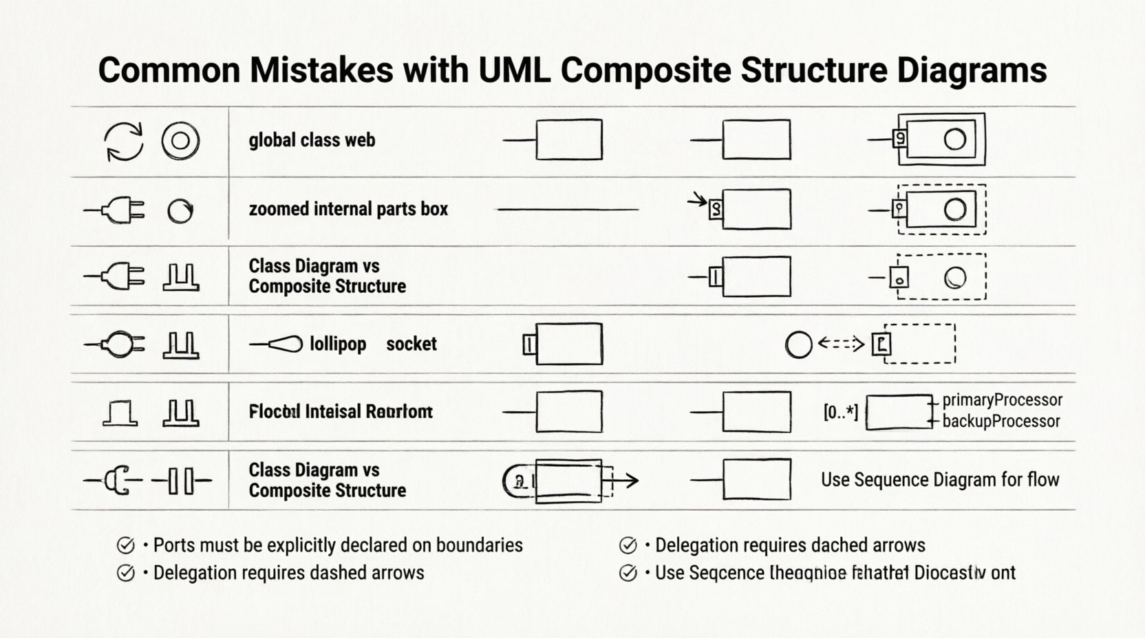
1. Confusing Composite Structure Diagrams with Class Diagrams 🔄
The most frequent error occurs when junior developers treat a Composite Structure Diagram as a standard Class Diagram. While both model structure, their focus differs significantly. A Class Diagram describes the static structure of a system through classes, attributes, and operations. It defines relationships like inheritance and association at the type level.
In contrast, a Composite Structure Diagram zooms in on a specific classifier. It reveals the internal parts that make up that classifier and how those parts interact. The confusion often stems from drawing internal parts as if they were standalone classes in a general view.
Why this distinction matters
Scope: Class diagrams show the global view. Composite structure diagrams show the internal view of a single component.
Visibility: Class diagrams focus on public interfaces. Composite diagrams focus on internal composition and private connections.
Implementation: Code generated from a Class Diagram defines types. Code derived from a Composite Structure Diagram defines how objects are assembled at runtime.
When a developer maps a composite diagram directly onto a class diagram without acknowledging the internal compartmentalization, the resulting code often lacks encapsulation. Internal parts become exposed, violating the principle of information hiding.
2. Misunderstanding Ports and Connectors 🔌
Ports and connectors are the defining features of a Composite Structure Diagram. A port represents a point of interaction between the internal structure and the external environment. Connectors define the communication path between ports.
Junior developers often omit ports entirely, drawing lines directly between parts. This simplifies the diagram visually but breaks the semantic meaning of the model. Without ports, the diagram cannot distinguish between internal interactions and external contracts.
Common Port Errors
Missing Notation: Failing to draw the small rectangle attached to the classifier boundary.
Incorrect Multiplicity: Assigning multiplicity to a port without defining the role it plays in the interaction.
Direct Lines: Connecting Part A to Part B without using a connector node. While internal links exist, the diagrammatic representation must show the connector explicitly.
Ports act as the boundary for delegation. If a part requires a service, it does not call the service directly. It requests it through a port. The connector then routes that request to the appropriate provider. Skipping this abstraction creates tight coupling in the model, which translates to tight coupling in the software.
3. Neglecting Provided and Required Interfaces 🧩
Interfaces define the contract of a port. Every port must specify whether it provides a service (lollipop notation) or requires a service (socket notation). A common oversight is leaving ports untyped. A port without an interface is functionally useless because the system cannot determine what operations are available.
The Interface Mismatch
Developers often assume that the interface is implied by the class type. This is incorrect. A part might have a specific class type, but its port must explicitly declare the interface it exposes.
Provided Interface: The part offers functionality. The diagram shows a lollipop attached to the port.
Required Interface: The part needs functionality. The diagram shows a socket attached to the port.
Delegation: If a part requires an interface, the port must delegate that requirement to the container or another part. This is often missed.
Without explicit interface declarations on ports, the diagram fails to communicate dependency. A maintainer cannot see which external systems are needed to support the internal parts.
4. Overlooking Delegation Connectors 🚪
Delegation connectors are specific to Composite Structure Diagrams. They link a port on the composite classifier to a part within that classifier. This mechanism allows the composite to expose the functionality of its internal parts to the outside world.
Juniors frequently draw connectors between parts but forget to link the composite classifier’s port to those parts. This breaks the delegation chain. The internal logic exists, but the external access point does not connect to it.
The Delegation Flow
External system calls a service on the Composite Classifier’s port.
The port delegates the request to an internal part.
The internal part executes the operation.
If the delegation connector is missing, the call stops at the port. The system thinks the operation is available, but no internal logic is triggered. This leads to runtime errors when the code attempts to execute the modeled behavior.
5. Misinterpreting Multiplicity and Roles 📏
Multiplicity defines how many instances of a part exist within the composite. Roles define the name of the part in the context of the relationship. Errors here often result in an incorrect mental model of the object lifecycle.
Common Multiplicity Mistakes
One-to-One Assumption: Assuming every part is a singleton. Many systems require a collection of parts (e.g., a list of processors in a server).
Zero-to-One Confusion: Failing to distinguish between an optional part and a mandatory part. A zero multiplicity means the part might not exist at runtime.
Role Names: Omitting role names makes it hard to distinguish between multiple instances of the same type. “Part A” and “Part B” are vague if they are both “Processor” types.
Correctly defining multiplicity ensures that the generated code handles instantiation logic correctly. If the diagram shows a multiplicity of 0..*, the code must support dynamic creation or null checks. If the diagram shows 1, the code assumes existence at initialization.
6. Mixing Interaction and Structure 🧱
Composite Structure Diagrams are static. They show structure, not behavior. A frequent error is adding dynamic elements like state transitions or sequence flow arrows within the structure diagram.
While connectors show potential communication, they do not show the order of operations. Mixing sequence diagrams with composite structure diagrams creates visual noise and confusion. The viewer cannot distinguish between structural dependency and temporal dependency.
Separation of Concerns
Structure: Use Composite Structure for parts, ports, and roles.
Behavior: Use Sequence or State Diagrams for flow and logic.
Interaction: Use Communication Diagrams for message flow between objects.
Keeping these concerns separate allows for better maintenance. If the structure changes, the structure diagram updates. If the logic changes, the behavior diagram updates. Blending them forces changes in one diagram to ripple into the other unnecessarily.
Comparison of Common Errors
Diagram Element | Common Mistake | Correct Practice |
|---|---|---|
Parts | Treating them as standalone classes | Define them as owned by the composite classifier |
Ports | Leaving them untyped or missing | Attach Provided or Required interfaces explicitly |
Connectors | Connecting parts directly without connectors | Use explicit connector nodes for all interactions |
Delegation | Forgetting to link ports to internal parts | Ensure external ports delegate to internal functionality |
Multiplicity | Defaulting to single instance | Specify exact cardinality (0..*, 1..1, etc.) |
Scope | Using it for global system overview | Use it only for specific composite classifiers |
7. Best Practices for Implementation 🛡️
To avoid these pitfalls, developers should adhere to a structured approach when modeling composite structures. The following guidelines ensure clarity and accuracy.
Start with the Classifier: Define the composite classifier first. This sets the context for all internal parts.
Define Interfaces First: Before drawing parts, define the interfaces they require and provide. This clarifies the contract before implementation.
Use Stereotypes: If standard UML notation is insufficient, use stereotypes to indicate specific types of parts (e.g., <<cache>>, <<db>>). This adds semantic meaning without clutter.
Limit Complexity: Do not nest composite structures indefinitely. A composite structure diagram should focus on one level of decomposition. If deeper detail is needed, create a new diagram for the nested part.
Review Multiplicity: Always double-check the cardinality of parts. Does the system allow the part to be absent? Does it allow multiple instances?
Validate Delegation: Trace the path from an external port to an internal operation. If the path is broken, the diagram is invalid.
8. When to Skip the Composite Structure Diagram 🚫
Not every system component requires a Composite Structure Diagram. Overusing this diagram type can lead to documentation bloat. It is best reserved for complex components where internal assembly is critical to understanding.
Indications that CSD is Unnecessary
Simple Classes: If a class has no internal parts, a Class Diagram is sufficient.
Behavior Focus: If the primary concern is the flow of data, a Sequence Diagram is more appropriate.
Low Complexity: If the component is a single unit of logic, internal structure adds no value.
High Level Architecture: For system-wide views, Component Diagrams are better suited than detailed Composite Structure Diagrams.
Using the right tool for the right job saves time. If a Class Diagram can convey the necessary information, do not force a Composite Structure Diagram into the workflow. This keeps the documentation focused and readable.
9. The Impact of Accurate Modeling 📊
Correctly modeling internal structures has tangible benefits for the development lifecycle. When the diagram accurately reflects the design, code generation tools can produce more reliable skeletons. Testers can derive test cases based on the defined interfaces and ports.
Furthermore, accurate diagrams reduce technical debt. When a developer encounters a bug, they can look at the diagram to see where data flows. If the diagram shows the correct delegation path, the search for the bug is narrowed to that specific interaction. If the diagram is wrong, the search becomes a guesswork exercise.
Investing time in learning the nuances of ports, connectors, and interfaces pays off. It shifts the developer from merely drawing boxes to understanding system composition. This deeper understanding is essential for maintaining scalable and modular software.
10. Summary of Key Takeaways ✅
Scope: Composite Structure Diagrams focus on internal composition, not global types.
Ports: Always define ports with interfaces (provided or required).
Connectors: Use explicit connectors for all interactions between parts and ports.
Delegation: Ensure external ports delegate requests to internal parts correctly.
Multiplicity: Specify exact cardinality for all parts to define lifecycle rules.
Separation: Do not mix behavioral flows into structural diagrams.
By recognizing these common errors, developers can produce diagrams that serve their intended purpose. The goal is clarity. A diagram that is difficult to read is a liability. A diagram that accurately captures the internal structure is a valuable asset. Focus on precision, avoid unnecessary complexity, and ensure every element in the diagram has a defined role in the system architecture.
Continuous review of these diagrams is necessary. As the system evolves, the internal structure may change. Keeping the model synchronized with the implementation ensures that documentation remains a source of truth rather than a relic of the past. This discipline is what separates robust engineering from ad-hoc development.

