


Designing complex software systems requires more than just listing classes and methods. It demands a deep understanding of how internal components interact to form a cohesive whole. This is where the UML Composite Structure Diagram becomes an indispensable tool. It reveals the internal architecture of a classifier, showing parts, ports, and connectors in a way that standard class diagrams cannot. When used effectively, this diagram type clarifies the boundaries and responsibilities within a system, ensuring that the design remains maintainable and scalable.
Creating these diagrams requires precision. A cluttered structure diagram can obscure more than it reveals. To achieve clarity, one must adhere to specific standards and organizational strategies. This guide outlines the necessary steps and principles for constructing robust models without relying on specific tools or proprietary features.
🔍 Understanding the Composite Structure Diagram
A Composite Structure Diagram focuses on the internal composition of a classifier. While a class diagram shows the static structure of the system, this diagram zooms in on a specific class or component to show how it is built from the inside out. It is particularly useful for:
- Visualizing Internal Architecture: Showing how parts make up a whole.
- Defining Interaction Points: Identifying where external systems connect to the internal logic.
- Managing Complexity: Breaking down large components into manageable sub-parts.
- Clarifying Interfaces: Distinguishing between what a part provides and what it requires.
The diagram is essentially a specialized form of a class diagram that allows for nested compartments. These compartments represent the internal structure of the classifier. By using this notation, architects can document the wiring and assembly of a system without needing to write extensive textual descriptions.
🧩 Core Components and Semantics
To create a clear diagram, one must understand the fundamental building blocks. Each element serves a specific purpose in defining the relationships and interactions.
1. Parts
A Part represents an instance of a classifier that is contained within the composite. It is similar to an attribute in a class diagram but is treated as a structural unit. Parts can be references to other objects or values. They form the composition hierarchy.
2. Ports
Ports are interaction points. They define where a part can communicate with the outside world or with other parts within the same composite. Ports are crucial for decoupling. Instead of connecting directly to an attribute, you connect to a port. This separation allows the internal implementation to change without breaking external connections.
3. Connectors
Connectors link ports together. They represent the interaction between parts. A connector can be a direct link between two ports or a link between a port and the external environment. They carry the flow of data or control signals.
4. Interfaces
Interfaces define the contract of interaction. A port is associated with an interface that specifies the operations available. Interfaces are typically represented as a lollipop shape (provided) or a socket shape (required).
5. Requirements and Deliverables
These elements are used to capture dependencies on external services or resources. A requirement indicates that the composite needs a certain capability to function. A deliverable indicates that the composite offers a capability to the rest of the system.
| Element | Function | Visual Representation |
|---|---|---|
| Part | Internal structural component | Rectangle with name and type |
| Port | Interaction boundary | Small rectangle attached to a part |
| Connector | Links parts or ports | Line connecting ports |
| Interface | Defines operations | Lollipop or Socket symbol |
| Composite | The containing classifier | Large bounding box or rectangle |
✅ Top Best Practices for Clarity
Clarity is the primary goal of any modeling effort. A diagram that is hard to read fails its purpose. The following practices ensure your diagrams communicate effectively.
1. Limit the Scope of Each Diagram
Do not attempt to model an entire system in a single composite structure diagram. Each diagram should focus on a specific classifier or a tightly coupled group of parts. If a diagram becomes too crowded, split it into multiple views. Use navigation or references to link related diagrams rather than cramming everything onto one canvas.
2. Use Ports for All External Interactions
One of the most common errors is connecting directly to attributes or methods. Always route interactions through ports. This enforces encapsulation. It ensures that the internal logic can evolve without requiring changes to the connectors. It also makes the dependencies explicit.
3. Maintain Consistent Naming Conventions
Consistency reduces cognitive load. Use a standard naming pattern for parts, ports, and interfaces. For example, prefix parts with the class name they belong to, or use a suffix to denote roles. Ensure that interface names match the operations they define. Inconsistent naming makes the diagram difficult to trace.
4. Avoid Deep Nesting Where Possible
While the diagram supports nested compartments, deep nesting can obscure the structure. If a part contains another composite that is itself complex, consider creating a separate diagram for the inner part. Reference that diagram instead of embedding the full structure. This keeps the main view clean.
5. Distinguish Between Provided and Required Interfaces
Visual distinction is vital. Clearly mark which interfaces are provided by a port and which are required. This helps readers understand the direction of dependency. A part that requires a service needs to find it elsewhere. A part that provides a service is offering it to others. Confusing these two leads to architectural errors.
6. Label Connectors with Roles
Connectors often carry data. Labeling them with the role they play helps understanding. For instance, a connector might be labeled “Input Stream” or “Control Signal”. This adds semantic value beyond just linking two boxes.
7. Document the State of Parts
If a part has a specific lifecycle or state machine, indicate this. While the diagram is structural, noting that a part is a “Singleton” or “Persistent” object adds valuable context. Use notes or stereotypes to convey this information without cluttering the diagram.
📉 Managing Complexity with Nested Compartments
The nested compartment is the defining feature of this diagram type. It allows you to show the internal wiring of a class. However, managing this complexity requires discipline.
- Top-Down Approach: Start with the high-level composite. Define the major parts first. Then, drill down into the details of specific parts in subsequent diagrams.
- Grouping: Group related parts together visually. Use bounding boxes or layout spacing to indicate logical groups. This helps the reader understand the hierarchy.
- Minimize Cross-Links: Try to keep connectors within the same compartment. If a connector must go outside, ensure it uses a port clearly defined at the boundary.
When parts are nested, the relationship becomes hierarchical. A part inside a part is a sub-component. Ensure the multiplicity is correct. A part might be optional (0..1) or mandatory (1). This affects how the system initializes.
🚫 Common Pitfalls to Avoid
Even experienced modelers can fall into traps that reduce the value of the diagram. Awareness of these common issues helps prevent them.
- Ignoring Ports: Drawing lines directly between parts without ports violates encapsulation. It implies the parts know each other’s internal details.
- Overusing Interfaces: Every part does not need a complex interface. Use simple interfaces for basic connections. Only use complex interfaces when there is a need for multiple operations.
- Mixing Concerns: Do not mix structural information with behavioral information in the same diagram. If you need to show state transitions, use a State Machine Diagram. If you need to show sequence of messages, use a Sequence Diagram.
- Redundant Information: Do not repeat information that is already present in the class diagram. Focus this diagram on the connections and composition, not the attributes and methods.
- Unclear Multiplicity: Leaving multiplicity undefined leads to ambiguity. Always specify how many instances of a part can exist within the composite.
🔄 Comparison: Internal Structure vs. Class Diagrams
It is easy to confuse this diagram with a standard Class Diagram. Understanding the distinction is key to choosing the right tool for the job.
- Class Diagram: Focuses on the attributes, operations, and general inheritance hierarchy. It is a high-level blueprint of the system.
- Composite Structure Diagram: Focuses on the assembly of parts. It shows how objects are composed to form a larger unit. It is more granular regarding instantiation.
- Usage: Use Class Diagrams for general design and documentation. Use Composite Structure Diagrams when the internal wiring of a specific component is complex and needs to be understood.
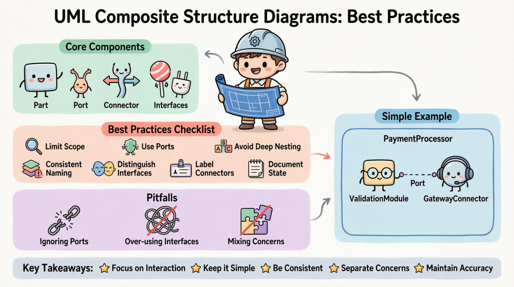
For example, if you have a “PaymentProcessor” class, the Class Diagram shows it has a “processPayment” method. The Composite Structure Diagram shows that the Processor contains a “ValidationModule” and a “GatewayConnector”. It shows how these parts talk to each other.
📝 Step-by-Step Creation Workflow
Follow a logical workflow to ensure the diagram is created systematically.
- Identify the Classifier: Choose the class or component you want to model. This will be the root of the composite.
- List the Parts: Identify all the sub-components that make up this classifier. Define their types.
- Define Interfaces: For each part, determine what operations it needs and what it offers. Create the interface definitions.
- Place Ports: Attach ports to the parts where interaction is required.
- Draw Connectors: Link the ports based on the interaction logic. Ensure the types match (provided to required).
- Review Multiplicity: Check the cardinality of each part and connector.
- Validate Consistency: Ensure the diagram aligns with the broader system architecture and other diagrams.
🛡️ Maintenance and Documentation
Once created, the diagram is not static. It must be maintained as the system evolves.
- Version Control: Treat the model like code. Track changes to the structure. If a part is removed, update the diagram immediately.
- Reference Links: If a diagram is large, create links to related diagrams. This creates a network of models rather than isolated islands.
- Annotations: Use notes to explain complex logic that cannot be shown visually. Keep these notes concise and relevant.
- Consistency Checks: Periodically review the diagram against the actual implementation. If the code changes, the diagram should reflect that change.
🎯 Summary of Key Takeaways
Creating clear UML Composite Structure Diagrams is about managing complexity through visual organization. By adhering to the practices outlined above, you ensure that your models serve their purpose effectively.
- Focus on Interaction: Use ports and connectors to define boundaries.
- Keep it Simple: Avoid deep nesting and clutter.
- Be Consistent: Follow naming and structural conventions.
- Separate Concerns: Do not mix structural and behavioral details.
- Maintain Accuracy: Keep the model synchronized with the code.
When these principles are applied, the resulting diagrams become powerful communication tools. They bridge the gap between abstract design and concrete implementation. They allow stakeholders to understand the internal logic of the system without getting lost in the code. This clarity is essential for long-term project success and system stability.
Invest time in getting the structure right. A well-designed diagram pays dividends in reduced confusion and faster development cycles. It serves as a reliable reference point for future modifications. By following this guide, you build a foundation for clear and effective system modeling.
")
