


Structural modeling is a cornerstone of robust system design. When you need to visualize the internal architecture of a classifier or show how parts collaborate to form a whole, the UML Composite Structure Diagram (CSD) provides the necessary depth. This diagram type goes beyond simple object relationships. It exposes the inner workings of a class or component, defining how it is constructed and how it interacts with its environment.
Understanding this diagram is essential for architects and engineers who need to specify complex systems. It bridges the gap between static structure and dynamic behavior by showing the assembly of parts. This guide explores every element, relationship, and best practice associated with composite structure diagrams.
What is a Composite Structure Diagram? 🤔
A Composite Structure Diagram represents the internal structure of a classifier. It shows the parts that make up the classifier, the roles those parts play, and the interfaces through which they communicate. Unlike a standard Class Diagram that focuses on attributes and methods, the CSD focuses on composition and connection.
This diagram is particularly useful when:
- Designing complex subsystems with multiple internal modules.
- Specifying hardware and software boundaries.
- Defining the assembly of components in a system architecture.
- Visualizing how a class is constructed from other classes.
The diagram provides a clear view of the internal block or internal structure of an element. It allows you to see the plumbing that connects different functional units.
Core Elements of the Diagram 🧱
To build a composite structure diagram, you must understand the fundamental building blocks. Each element serves a specific purpose in defining the system’s topology. Below is a breakdown of the primary components.
1. Parts 🧩
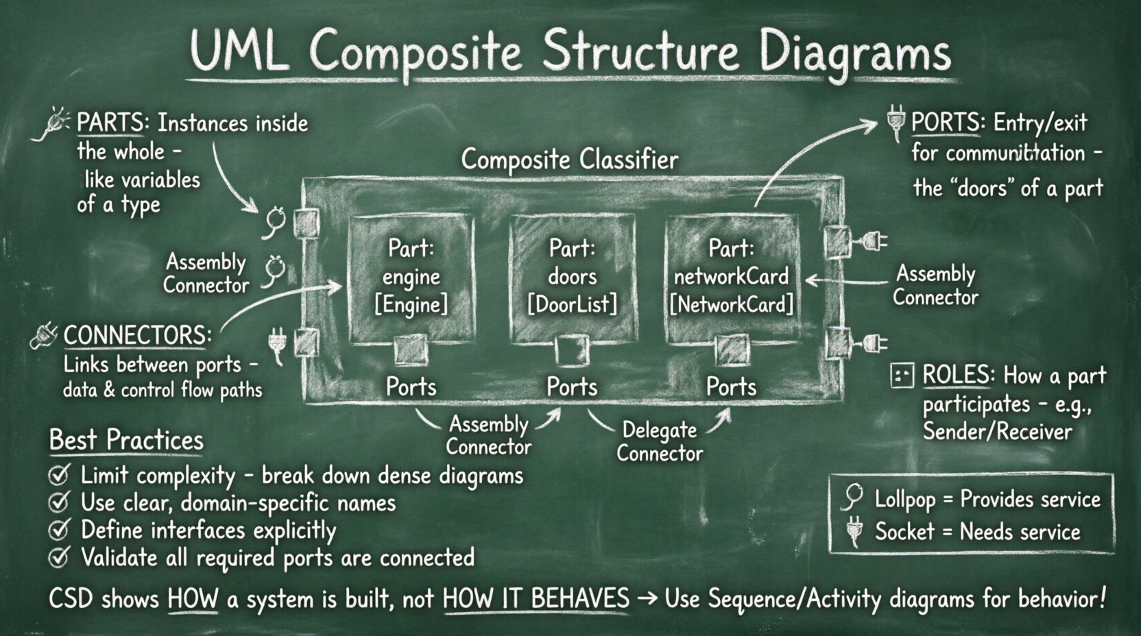
A Part represents an instance of a classifier within the composite structure. It is a component of the whole. Parts are the physical or logical units that reside inside the container. You can think of a part as a variable declaration of a specific type within the scope of the composite class.
- Notation: A rectangle with a name and type, often placed inside the main container.
- Example: Inside a
Carclassifier, you might have parts likeengineof typeEngineanddoorsof typeDoorList.
2. Ports 🔌
Ports are the entry and exit points for communication. A part cannot interact directly with the outside world; it must go through a port. Ports define the interaction points where the internal part connects to the external environment or other internal parts.
- Provided Interface: A port that offers functionality to others. Often shown as a lollipop icon.
- Required Interface: A port that needs functionality from others. Often shown as a socket icon.
3. Connectors 🔗
Connectors establish communication paths between ports. They represent the links that allow data, control signals, or material to flow between parts. Connectors ensure that the parts are not isolated silos but form a cohesive system.
- Assembly Connectors: Connect a required interface to a provided interface.
- Delegate Connectors: Delegate the interaction from the composite’s external port to an internal part’s port.
4. Roles 🎭
A Role describes the perspective from which a part participates in a connection. A single part might play multiple roles in different connections. For example, a NetworkCard part might play the role of Sender in one connection and Receiver in another.
Visualizing Interfaces and Interactions 📊
Interfaces are critical for decoupling the internal implementation from the external usage. A Composite Structure Diagram relies heavily on interface definitions to maintain flexibility.
| Element | Symbol | Description |
|---|---|---|
| Part | Rectangle with label | An instance of a classifier contained within the structure. |
| Port | Small square on the border of a Part | A boundary through which a part interacts with others. |
| Provided Interface | Lollipop (Circle on stick) | Indicates that the port provides a service. |
| Required Interface | Socket (Half-circle) | Indicates that the port requires a service. |
| Connector | Line connecting ports | Establishes a link between two ports. |
| Composite Structure | Large Rectangle | The container representing the classifier. |
Internal Block Diagram vs. Composite Structure Diagram 🔄
In the Unified Modeling Language (UML), there is often confusion between the Composite Structure Diagram and the Internal Block Diagram (IBD). While they share similarities, their contexts differ.
- Composite Structure Diagram: Focuses on the classifier structure. It is used to define the internal structure of a Class or Component. It is often used during the design phase to define the architecture of a specific entity.
- Internal Block Diagram: Focuses on the block structure. It is used within Activity Diagrams or Sequence Diagrams to show the data flow between blocks during a specific behavior. It is more dynamic in nature.
Both diagrams use similar notation for parts and ports, but their semantic context varies. The CSD is static structural modeling, while the IBD often supports behavioral modeling.
Defining Relationships and Dependencies 🔗
Establishing correct relationships is vital for the integrity of the model. You must ensure that dependencies are accurately reflected to avoid circular logic or undefined behavior.
Usage and Realization
Interfaces define contracts. When a part requires a service, it uses a Usage relationship. When a part provides a service, it uses a Realization relationship. These relationships clarify the direction of dependency.
Delegation
Delegation is a specific type of connector. It connects a port of the composite structure to a port of an internal part. This allows the composite to expose the functionality of its internal parts to the outside world without revealing the internal topology in detail.
For example, if a UserInterface part needs to send a command to a Processor part, the composite class might have a port that delegates this call directly to the Processor. This maintains encapsulation while enabling necessary communication.
Modeling Best Practices ✅
To create effective diagrams that serve their purpose, adhere to these guidelines.
- Limit Complexity: A single diagram should not contain too many parts. If the structure becomes too dense, consider breaking it down into multiple diagrams or using sub-composites.
- Consistent Naming: Use clear names for parts and ports. Avoid generic names like
part1orconn1. Use domain-specific terminology. - Define Interfaces Clearly: Do not assume interfaces are known. Explicitly define the operations or signals that are provided or required.
- Use Roles: If a part is reused in different contexts, define roles to show its specific function in each connection.
- Validate Connectivity: Ensure that every required port has a matching provided port connected via a connector. Unconnected required ports indicate a missing dependency.
Common Pitfalls and Troubleshooting ⚠️
Even experienced modelers encounter issues. Being aware of common mistakes helps maintain model quality.
Over-Modeling
It is tempting to show every single attribute and method in the composite structure. This is unnecessary. Focus on the structural connections. Attributes are usually better represented in the Class Diagram or the Part details.
Confusing Parts and Instances
A Part in a CSD is a structural component, not necessarily a runtime instance. While related, the distinction matters. The CSD defines the blueprint. The runtime environment creates the instances.
Nested Structures
While nesting parts is allowed, excessive nesting makes the diagram unreadable. If you find yourself nesting parts within parts within parts, consider flattening the hierarchy or creating a separate diagram for the nested component.
Integration with Other UML Diagrams 📐
The Composite Structure Diagram does not exist in isolation. It interacts with other diagram types to provide a complete system view.
- Class Diagram: The CSD provides the internal view of a Class defined in the Class Diagram. The Class Diagram defines the static attributes and operations, while the CSD defines how that class is assembled.
- Deployment Diagram: The CSD helps define the software components that will be deployed. It clarifies the internal composition before mapping to hardware nodes.
- Sequence Diagram: The ports defined in the CSD become the participants in interaction sequences. You can verify that the message flow in a Sequence Diagram aligns with the port definitions in the CSD.
Advanced Scenarios 🚀
Complex systems often require advanced modeling techniques. Here are scenarios where the CSD shines.
Hardware-Software Co-Design
When designing embedded systems, you often have both software modules and hardware chips. The CSD can model this hybrid structure. You can define a FPGA part alongside a Driver software part, showing how they connect via a port.
Subsystem Decomposition
Large systems are divided into subsystems. The CSD allows you to define a subsystem as a composite structure containing other subsystems. This hierarchical approach helps manage complexity in enterprise-level architectures.
Stateful Components
Sometimes parts need to maintain state. While the CSD primarily shows structure, the parts involved can be associated with State Machine Diagrams. This shows how the internal structure manages state transitions.
Frequently Asked Questions 🤔
Can I use Composite Structure Diagrams for dynamic behavior?
No. This diagram is strictly for structural modeling. It shows how the system is built, not how it behaves over time. For behavior, use Sequence, Activity, or State Machine diagrams.
How do I handle multiple interfaces on one port?
A port can support multiple interfaces. You can draw multiple lollipops or sockets on the same port, or use a single port with a label indicating it supports multiple interfaces. Ensure the connector connects to the specific interface needed.
Is this diagram supported in SysML?
Yes. The SysML Internal Block Diagram is derived from the UML Composite Structure Diagram. While SysML focuses more on IBD, the concepts of parts, ports, and connectors remain identical.
What is the difference between a Part and a Property?
In the context of a Class, a Property is an attribute. In the context of a Composite Structure Diagram, a Part is a structural component. They are similar but used in different modeling contexts. Parts imply a composition relationship.
Do I need to show all parts?
No. You can omit parts that are not relevant to the current architectural view. However, omitting critical parts may lead to confusion about system dependencies. Show only what is necessary for the specific design goal.
How do I represent data flow?
Data flow is implied by the connectors. If you need to show specific data types, you can label the connector with the data type name. However, for detailed data flow, a Sequence or Activity Diagram is more appropriate.
Can parts be aggregated?
Yes. Parts can be connected via aggregation relationships. This indicates that a part can exist independently of the composite structure, depending on the cardinality and relationship type defined.
Summary 📝
The UML Composite Structure Diagram is a powerful tool for defining the internal architecture of complex systems. By breaking down a classifier into parts, ports, and connectors, you gain clarity on how components interact. This clarity reduces ambiguity during implementation and testing.
Key takeaways include:
- Parts represent the components inside a structure.
- Ports define the interaction points.
- Connectors link ports to enable communication.
- Interfaces ensure decoupling between components.
- Consistent modeling practices prevent structural errors.
When applied correctly, this diagram supports better collaboration between architects, developers, and testers. It serves as a contract for the internal design, ensuring that all parties understand the assembly of the system. Focus on clarity, accuracy, and relevance when creating these diagrams to maximize their value in your engineering workflow.

