


Understanding the internal architecture of complex systems is crucial for any software engineer or system designer. While standard class diagrams show relationships between objects, they often fail to depict how a specific component is internally constructed. This is where the UML Composite Structure Diagram becomes indispensable. It provides a granular view of the internal parts of a classifier and how those parts interact. This guide breaks down the visual language of these diagrams, enabling you to interpret system boundaries, interfaces, and connections quickly.
Whether you are reviewing legacy code documentation or designing a new microservice architecture, knowing how to parse this diagram type saves time and reduces ambiguity. We will move through the anatomy, symbols, and reading strategies required to understand these structures without needing to open a specific modeling tool.
What Is a Composite Structure Diagram? 🤔
A Composite Structure Diagram represents the internal structure of a classifier, such as a class or component. It shows how the internal parts are assembled to form the whole. Unlike a Component Diagram, which focuses on software modules and their deployment, the Composite Structure Diagram zooms in to show the parts inside a single unit.
- Focus: Internal organization of a classifier.
- Scope: Shows parts, ports, and connectors.
- Goal: Clarifies how responsibilities are delegated within a system.
This diagram is particularly useful when a class has significant internal complexity that cannot be conveyed through inheritance or association lines alone. It answers the question: “What makes up this object, and how do those pieces talk to each other?”
The Core Building Blocks 🧱
To read this diagram effectively, you must recognize the fundamental shapes and lines used. Each element has a specific semantic meaning in the Unified Modeling Language (UML) standard.
1. The Classifier Boundary
The diagram is typically contained within a large rectangle. This rectangle represents the Composite Structure itself. It acts as a container for all internal parts.
2. Parts and Roles
Inside the boundary, you will see smaller rectangles representing Parts. A part is an instance of a classifier that is owned by the composite structure.
- Part Name: The specific name of the instance.
- Part Type: The class or interface it belongs to.
- Role Name: The name the part plays in the relationship.
3. Ports
Ports are the points of interaction. They are small squares or circles attached to the boundary of a part. They define where a part can accept or provide services.
4. Connectors
Lines that join parts to other parts or ports. These represent the flow of data or control signals between internal components.
Decoding the Symbols 🔍
Visual literacy is key to reading UML. Below is a structured reference for the most common symbols you will encounter.
| Symbol | Name | Meaning |
|---|---|---|
| Rectangle with dashed line | Part | An instance of a class owned by the composite. |
| Small square on a part | Port | A distinct point of interaction for a part. |
| Line connecting ports | Connector | Establishes a communication path between parts. |
| Line with open arrow | Usage Dependency | Indicates one part uses another part’s functionality. |
| Line with filled diamond | Composition | Strong ownership; parts cannot exist without the whole. |
| Line with hollow diamond | Aggregation | Weak ownership; parts can exist independently. |
A Step-by-Step Reading Strategy 📖
Attempting to read every line at once can be overwhelming. Instead, follow this systematic approach to deconstruct the diagram logically.
Step 1: Identify the Context
Locate the main rectangle. Read its label. This tells you what system or class you are analyzing. For example, if the label is OrderProcessor, you are looking at the internal makeup of that processor.
Step 2: Analyze the Parts
List all the rectangles inside the main boundary. Note their types. Are they standard classes? Interfaces? Other components? This establishes the inventory of resources available within the system.
- Check Ownership: Are these parts optional or mandatory?
- Check Multiplicity: Is there one instance, or many?
Step 3: Trace the Connections
Follow the lines connecting the parts. Determine the direction of flow.
- Delegation Connectors: These connect a part’s port to the composite structure’s port. This means the composite forwards requests to the part.
- Standard Connectors: These connect parts directly to other parts. This implies internal processing logic.
Step 4: Check Interfaces
Look for lollipop symbols (provided interfaces) and half-circle symbols (required interfaces). These define the contract between the composite and the outside world, or between internal parts.
Step 5: Validate Constraints
Check for notes or constraints attached to parts or connectors. These often contain logic rules, such as “Part A must be initialized before Part B”.
Understanding Interfaces 🎯
Interfaces are the most critical aspect of composite structures. They define how a part exposes functionality to the rest of the system.
Provided Interfaces
Also known as a Service. When a part provides an interface, it is saying, “I can do this job.” Visually, this is often a circle (lollipop) on a port.
Required Interfaces
Also known as a Usage. When a part requires an interface, it is saying, “I need this job done to function.” Visually, this is a half-circle (socket) on a port.
The Interaction Pattern
Read the diagram by matching sockets to lollipops. If a required interface connects to a provided interface, the dependency is satisfied. If it connects to a port on the main boundary, the composite delegates that requirement to the outside world.
Common Structural Patterns 🏗️
Experienced readers recognize recurring patterns. Identifying these patterns helps you predict behavior without analyzing every single line.
1. The Delegation Pattern
This is the most common pattern in this diagram type. A part handles a specific task, and the main composite structure delegates requests to it.
- Why use it? It hides complexity. The outside world sees the composite, not the internal parts.
- Visual cue: A connector from the composite port to the part port.
2. The Nested Structure
Parts can contain other parts. This creates a hierarchy of responsibility.
- Why use it? It models complex subsystems within a subsystem.
- Visual cue: A part rectangle containing another part rectangle.
3. The Redundancy Pattern
Multiple parts of the same type working together.
- Why use it? It increases reliability or performance.
- Visual cue: Multiple parts with the same type name connected to a central controller.
Why This Matters for Architecture 🏗️
Understanding this diagram goes beyond syntax. It impacts how you design, debug, and scale systems.
- Boundary Definition: It clearly separates internal logic from external contracts.
- Decoupling: By using ports and interfaces, parts can change without breaking the whole.
- Refactoring: It helps identify where to extract a new component from an existing monolithic class.
When reviewing a design document, this diagram tells you if the internal cohesion is high. If parts are loosely connected or if the boundary is cluttered, the design may need simplification.
Tips for Clear Communication 🗣️
If you are creating these diagrams for a team, clarity is paramount. Follow these guidelines to ensure your diagrams are readable.
- Name Ports Clearly: Avoid generic names like “port1”. Use names like “authService” or “dataWriter”.
- Group Related Parts: Use visual grouping or sub-structures to show logical clusters.
- Limit Complexity: If a diagram has more than 15 parts, consider splitting it into multiple diagrams.
- Use Stereotypes: Indicate if a part is a database, a cache, or a service using standard stereotypes.
Common Pitfalls to Avoid 🚫
Even experienced designers make mistakes when modeling composite structures. Be aware of these common errors.
- Overusing Composition: Not every internal part needs to be owned by the composite. Sometimes parts are shared.
- Ignoring Lifecycle: Do not forget to specify if parts survive the death of the composite.
- Confusing Components: Do not mix Component Diagram syntax with Composite Structure syntax. Keep the focus on internal structure, not deployment.
- Missing Interfaces: If a part interacts with the outside, it needs a port. Missing ports create ambiguity about data flow.
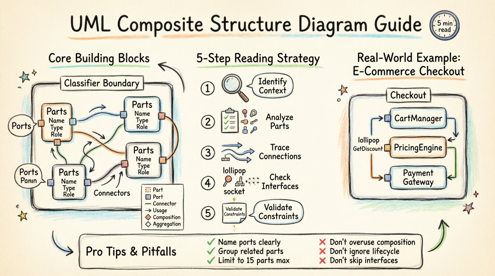
Real-World Application Example 🌐
Imagine designing an E-commerce Checkout System. The Checkout composite structure might contain:
- Part 1:
CartManager– Handles the items. - Part 2:
PricingEngine– Calculates totals. - Part 3:
PaymentGateway– Processes money.
In the diagram, Checkout would have a port for InitiatePayment. This port would delegate to the PaymentGateway part. The PricingEngine would require a GetDiscount interface from an external service.
This structure shows exactly how the checkout process flows internally. It reveals that the PaymentGateway is a critical dependency. If PaymentGateway fails, the Checkout cannot complete. This visibility is vital for error handling strategies.
Best Practices for Designers 📝
To maintain high standards in your documentation, apply these practices consistently.
- Consistent Naming: Ensure part names match the code variable names as closely as possible.
- Layering: Use the diagram to show logical layers, not just physical files.
- Versioning: Update the diagram whenever the internal structure changes. Stale diagrams are worse than no diagrams.
- Documentation: Add notes to explain complex logic that cannot be shown visually.
Final Thoughts on Mastery 🎓
Reading a UML Composite Structure Diagram is a skill that improves with practice. It requires attention to detail and an understanding of object-oriented principles. By mastering the symbols, understanding the flow of data through ports, and recognizing structural patterns, you gain a deeper insight into system design.
This diagram type bridges the gap between high-level architecture and low-level implementation. It ensures that the internal complexity of a system is documented and visible to all stakeholders. Whether you are debugging a production issue or planning a new feature, the ability to read these structures quickly is a significant asset in your technical toolkit.
Start by analyzing existing diagrams in your project. Identify the parts, trace the connectors, and verify the interfaces. Over time, you will find that these diagrams become a natural extension of your thinking process, helping you build more robust and maintainable software systems.
Remember, the goal is clarity. A well-constructed composite structure diagram tells a story about how a system works. Your job is to read that story accurately and efficiently.

