


Software architecture is the backbone of any complex system, yet it often becomes a source of confusion rather than clarity. When teams struggle to communicate design decisions, technical debt accumulates, and onboarding new members slows down. The C4 Model provides a structured approach to documenting software architecture. It moves away from vague diagrams toward a clear hierarchy of abstraction. This method ensures that every stakeholder sees the right level of detail for their needs.
Documentation often fails because it tries to do too much at once. It either overwhelms the audience with code-level details or remains too high-level to be useful. The C4 Model solves this by breaking architecture down into four distinct levels. Each level answers a specific question about the system. By using this toolkit, teams can create living documentation that evolves with the software.
The Architecture Communication Challenge 🧱
Building software is a team effort. Developers, product managers, stakeholders, and operations engineers all need to understand the system. However, their perspectives differ significantly. A stakeholder cares about business value and external interactions. A developer cares about how code modules interact. A database administrator cares about data flow and storage.
Traditional documentation often tries to serve all these audiences with a single diagram. This approach rarely works. A single complex diagram becomes a maze that no one can navigate. It leads to miscommunication and errors. The C4 Model addresses this by separating concerns. It creates a layered view of the system.
Here are the core problems this model solves:
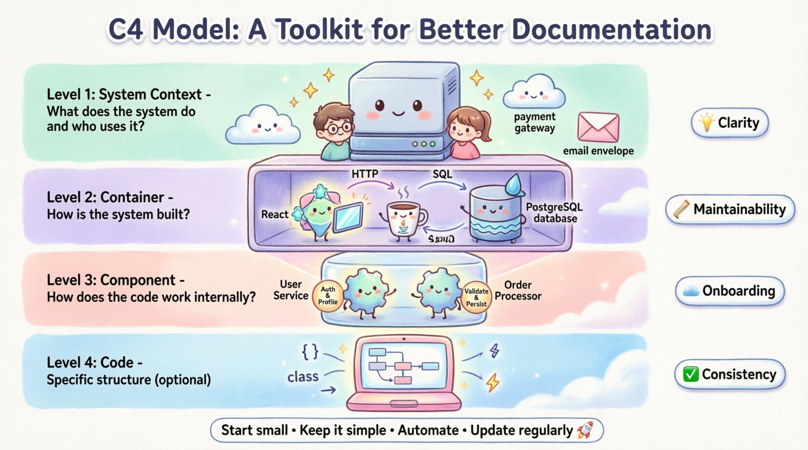
- Clarity: It separates high-level business context from low-level implementation details.
- Maintainability: It is easier to update a specific layer without rewriting the entire document.
- Onboarding: New team members can start with the high-level view and drill down as needed.
- Consistency: It provides a standard language for describing architecture across the organization.
The Four Levels of Abstraction 📊
The C4 Model defines four specific levels of detail. Each level serves a different audience and purpose. Understanding the distinction between these levels is key to effective documentation. The hierarchy flows from the outside world down to the code.
The following table outlines the scope and focus of each level:
| Level | Diagram Type | Focus | Primary Audience |
|---|---|---|---|
| Level 1 | System Context | System and external users | Stakeholders, Architects |
| Level 2 | Container | High-level technical structure | Developers, Project Managers |
| Level 3 | Component | Internal software structure | Developers, Tech Leads |
| Level 4 | Code | Class and code relationships | Senior Developers |
Level 1: System Context Diagram 🌍
The journey begins with the System Context diagram. This is the highest level of abstraction. It shows the software system as a single box in the middle. Surrounding this box are the people and systems that interact with it.
This diagram answers the question: What does the system do, and who uses it? It does not show internal workings. It focuses purely on boundaries and interactions.
Key Elements of a Context Diagram
- The System: Represented as a central box with a clear name.
- Users: People or roles that interact with the system (e.g., Admin, Customer).
- External Systems: Other software systems that communicate with your system (e.g., Payment Gateway, Email Service).
- Connections: Lines showing how data flows between the system and the external entities.
When creating this diagram, keep it simple. Avoid showing too many external dependencies. Focus on the critical paths that define the system’s value. This diagram is often the first thing a new hire looks at to understand the business scope.
Level 2: Container Diagram 📦
Once the context is established, the next step is to look inside the box. The Container diagram breaks the system down into major building blocks. In software terms, a container is a deployed unit of code. Examples include web applications, mobile apps, databases, and microservices.
This diagram answers the question: How is the system built? It focuses on the technology stack and the high-level data flow.
Key Elements of a Container Diagram
- Containers: Distinct runtime environments (e.g., Java Application, PostgreSQL Database, React Frontend).
- Technologies: Briefly note the language or framework used for each container.
- Connections: Show how containers communicate (e.g., HTTP, SQL, Message Queue).
- Data Stores: Indicate where data is persisted.
This level is crucial for architects and senior developers. It helps them understand the boundaries of services and the protocols used for communication. It prevents the common pitfall of building monolithic structures when a distributed approach is needed.
Level 3: Component Diagram ⚙️
Inside a container, there is structure. The Component diagram zooms in further. It shows the internal structure of a single container. It breaks the container down into functional components.
This diagram answers the question: How does the code work internally? It is more abstract than code, focusing on logic rather than implementation details.
Key Elements of a Component Diagram
- Components: Logical groupings of functionality (e.g., User Service, Order Processor).
- Responsibilities: What each component does (e.g., “Handles authentication”, “Calculates totals”).
- Interfaces: How components talk to each other (APIs, methods).
- Dependencies: What external libraries or other components are required.
This level is most useful during the design phase of a specific feature. It helps developers plan the internal architecture before writing code. It ensures that responsibilities are separated and that the system remains maintainable.
Level 4: Code Diagram 💻
The final level dives deep into the implementation. The Code diagram shows classes, interfaces, and methods. It is often generated automatically from the codebase.
This diagram answers the question: What is the specific structure of the code? It is rarely maintained manually because code changes frequently.
When to Use Code Diagrams
- Complex Logic: When algorithms are intricate and need visual explanation.
- Legacy Systems: To understand existing code where documentation is missing.
- Onboarding: To help developers quickly grasp class hierarchies.
Because code changes constantly, relying on manual updates for this level is unsustainable. Automated tools are preferred here. The C4 Model suggests that Level 4 is optional for many projects. It is only necessary when the complexity demands it.
Benefits for Teams and Stakeholders 🔍
Adopting this structured approach brings tangible value to the organization. It is not just about drawing pictures; it is about improving communication.
1. Improved Onboarding Experience
New team members often struggle to understand a codebase. With the C4 Model, they start with the Context diagram. They understand the business goal first. Then they move to Containers to understand the stack. Finally, they look at Components for specific logic. This path reduces the time to productivity.
2. Better Decision Making
When architects have clear diagrams, they can identify risks earlier. They can see where dependencies are too tight. They can spot where data flows are inefficient. This proactive approach reduces technical debt.
3. Alignment Between Teams
Development teams, operations, and product managers often speak different languages. The C4 Model provides a visual language that everyone understands. It aligns technical decisions with business goals.
4. Easier Maintenance
When a system needs a change, the diagrams help identify the impact. If a database container changes, the diagram shows which services depend on it. This prevents accidental breakages during updates.
Implementing the Model in Your Workflow 🔄
Introducing a new documentation standard requires a plan. It should not be a burden. It should be integrated into the existing development process.
Start Small
Do not attempt to document every single system at once. Pick one critical system or a new project. Create the Level 1 and Level 2 diagrams first. These provide the most value for the least effort.
Integrate with Design Reviews
Make diagrams part of the design review process. Before writing code, draft the Component diagram. This ensures the design is sound before implementation begins.
Keep it Simple
Do not over-engineer the diagrams. If a diagram is confusing, simplify it. Use standard shapes and clear labels. Avoid clutter. The goal is communication, not art.
Automate Where Possible
Use tools that can generate diagrams from code or configuration files. This ensures the documentation stays in sync with the actual system. Manual updates lead to outdated information quickly.
Maintenance and Evolution 🌱
Documentation is not a one-time task. It is a living asset. As the software evolves, the diagrams must evolve too.
Update Triggers
- New Features: When a new feature changes the architecture, update the relevant level.
- Refactoring: If code is reorganized, update the Component diagram.
- Infrastructure Changes: If a database is replaced, update the Container diagram.
Version Control
Store diagrams in the same repository as the code. This ensures they are versioned alongside the software. It makes it easy to see how the architecture changed over time.
Review Cycles
Schedule regular reviews of the documentation. Once a quarter, check if the diagrams match the current state of the system. This keeps the documentation reliable.
Avoiding Common Documentation Traps ⚠️
Even with a good model, teams can make mistakes. Being aware of these pitfalls helps maintain high-quality documentation.
1. Over-Documentation
Creating diagrams for every single class or minor detail wastes time. Focus on the levels that matter. Usually, Level 1 and Level 2 are sufficient for most stakeholders.
2. Inconsistent Naming
Ensure that names in the diagrams match the code. If a service is called “User Service” in the diagram, the code should reflect that. Consistency reduces confusion.
3. Ignoring the Audience
Do not show a Level 4 diagram to a product manager. Tailor the detail level to the reader. Context diagrams for business, Container diagrams for architects.
4. Static Documents
Do not save diagrams as static images in a wiki and forget them. They become outdated quickly. Treat them as code. Keep them in version control and update them with every major change.
Conclusion
Effective documentation is a skill that requires discipline and clarity. The C4 Model offers a proven framework for achieving this. It structures information logically, ensuring that every stakeholder gets the right view. By adopting this toolkit, teams can build software that is easier to understand, maintain, and scale.
Start with the Context. Drill down to the Containers. Detail the Components. Use the Code diagrams only when necessary. Follow this path, and your documentation will become a valuable asset rather than a chore. 🚀

