


Software systems grow. Features are added, services are split, and integrations multiply. Without a clear map, the architecture becomes a tangled web of logic that is difficult to navigate, maintain, or explain to stakeholders. This is where the C4 Model enters the picture. It provides a structured approach to documenting software architecture, breaking down complexity into manageable layers of abstraction.
The goal is not just to draw pictures, but to communicate intent, structure, and behavior. By using a consistent set of diagrams, teams can align on how the system works without getting lost in implementation details too early. This guide explores the four levels of the C4 Model, how to apply them effectively, and the principles that keep your documentation useful over time.
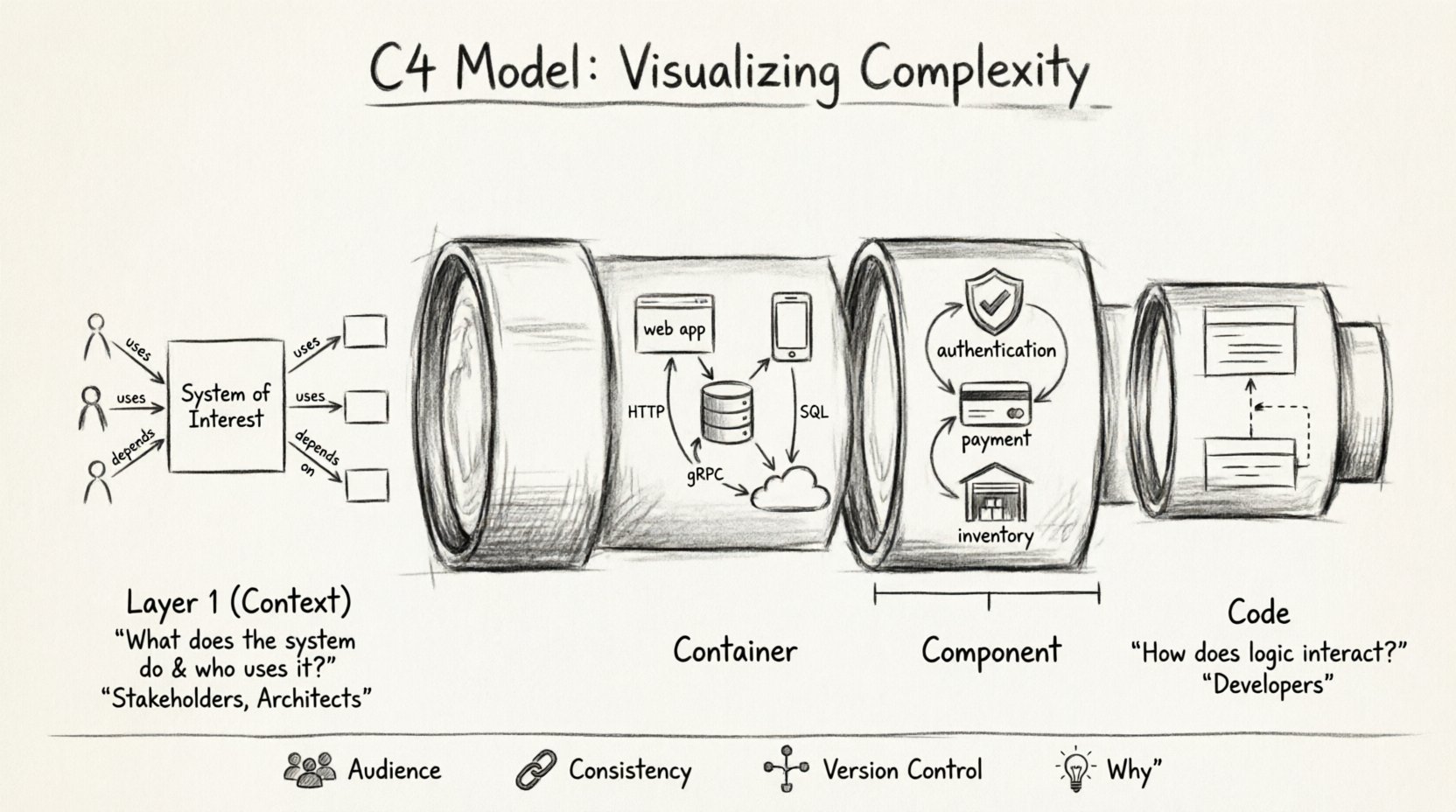
🧩 Understanding the C4 Model Framework
The C4 Model is a hierarchy of software architecture diagrams. It stands for Context, Container, Component, and Code. Each level represents a different level of abstraction, tailored to a specific audience and purpose. Instead of one massive diagram trying to show everything, the model encourages a layered view.
Level 1: Context Diagram 🌍
Level 2: Container Diagram 📦
Level 3: Component Diagram ⚙️
Level 4: Code Diagram 💻
This structure allows you to zoom in on specific parts of the system only when necessary. It prevents the cognitive overload that comes from trying to understand every line of code in a high-level overview. The model is technology agnostic, meaning it does not depend on specific programming languages or frameworks.
📉 The Hierarchy of Abstraction
Choosing the right level of detail is critical. A diagram that is too high-level fails to provide technical guidance. A diagram that is too detailed overwhelms the reader. The table below outlines the distinction between the four levels, including the intended audience and the typical scope.
Level | Focus | Primary Audience | Key Question Answered |
|---|---|---|---|
Context | System boundaries and relationships | Stakeholders, Customers, Architects | What does the system do and who uses it? |
Container | High-level technical structure | Developers, DevOps, Architects | What technologies are used and how do they communicate? |
Component | Logical breakdown of a container | Developers, Team Leads | How is the code organized inside a container? |
Code | Class-level structure and logic | Developers | How does the logic interact within a class or module? |
Not every system requires all four levels. A small application might only need a Context and Container diagram. A large enterprise system with complex logic might benefit from the Component and Code levels. The key is to start high and drill down only when the abstraction leaks or the details become necessary for decision-making.
🌍 Level 1: The Context Diagram
The Context Diagram is the starting point. It defines the System of Interest and shows how it fits into the broader ecosystem. This diagram is often the first thing a new team member looks at to understand the landscape.
Key Elements
System of Interest: The main application or service being documented. This is usually represented as a box in the center.
People: Users or roles that interact with the system. These can be internal users, external customers, or administrators.
Systems: Other software systems that the main system communicates with. These are external dependencies or integrations.
Relationships: Lines connecting people and systems to the main box. These lines are labeled to describe the type of interaction (e.g., “Manages”, “Consumes”, “Provides”).
Best Practices for Context Diagrams
Keep it simple: Do not include every single database or microservice unless it is a critical integration point.
Focus on boundaries: Clearly define what is inside your system and what is outside.
Use labels: Arrows should have text describing the data flow or action. A line without a label is ambiguous.
Color coding: Use colors to distinguish between different types of actors, such as humans versus other software systems.
When creating this diagram, the question is not “how does it work?” but rather “what is it?”. It sets the stage for all subsequent diagrams. If the Context Diagram is confusing, the detailed diagrams below it will likely suffer from the same issue.
📦 Level 2: The Container Diagram
Once the context is established, the Container Diagram dives into the technical structure. A container is a high-level building block, such as a web application, a mobile app, a database, or a microservice. It is a distinct, deployable unit of software.
What is a Container?
A container is not a Docker container in the strict sense, although it can be one. It is any distinct runtime environment. Common examples include:
A web server running HTML and CSS.
A Java Virtual Machine executing a JAR file.
A PostgreSQL database instance.
A serverless function deployed to the cloud.
A mobile application installed on a phone.
The Container Diagram shows how these containers relate to each other. It focuses on the technology choices and the communication protocols between them.
Key Elements
Containers: Represented as boxes, often with a specific icon or color to denote the technology (e.g., a database icon for SQL).
Connections: Lines indicating communication. These should specify the protocol, such as HTTP, gRPC, TCP, or SQL.
Technology Stack: Labels indicating the language or framework used (e.g., “React”, “Python”, “MySQL”).
Strategic Value
This level is crucial for DevOps and infrastructure teams. It helps answer questions about deployment, scaling, and security. If you are planning a migration from a monolithic architecture to microservices, this diagram is the blueprint for that transition. It helps identify single points of failure and bottlenecks in data flow.
When drawing this, avoid showing internal logic. Do not show classes or functions. Keep the view at the system boundary. If a container is complex, you can create a separate Component Diagram for it.
⚙️ Level 3: The Component Diagram
When a container becomes too large to understand as a single block, you move to the Component level. This diagram breaks down a container into its internal parts. Components are logical groupings of functionality, such as a module, a package, or a service within the application.
Defining Components
Components are defined by their behavior and interface, not their implementation. A component might handle authentication, process payments, or manage inventory. The goal is to show how responsibilities are distributed within the container.
Logical Structure: Shows how the code is organized into manageable chunks.
Dependencies: Shows which components rely on others. This helps in understanding coupling and cohesion.
Interfaces: Defines how components talk to each other within the same container.
When to Use This Level
This level is typically used by the development team working on specific features. It helps onboarding new developers by showing where their code fits. It is also useful for identifying architectural debt. If you see many components depending on a single central component, you might have a bottleneck or a “God Object” that needs refactoring.
It is important to maintain consistency between the Container and Component diagrams. If a new container is added at Level 2, the corresponding Component diagrams must be updated to reflect where that container fits within the broader system.
💻 Level 4: The Code Diagram
The Code Diagram is the most detailed view. It shows the internal structure of a component, often at the class or function level. While the C4 Model is primarily for architecture, this level can be useful for complex algorithms or critical logic paths.
Limitations and Considerations
Maintainability: Code changes frequently. Diagrams that are too close to the code become outdated quickly.
Tooling: Generating these diagrams automatically from source code is common, but manual curation is often required to make them readable.
Scope: Only diagram critical paths. Do not try to document every class in the system.
Most teams use this level sparingly. It is often better to rely on code comments and documentation for this level of detail. However, for complex algorithms, a visual representation can clarify the flow of data better than reading the code itself.
📐 Principles for Effective Diagramming
Creating diagrams is an art. The goal is clarity, not aesthetics. Here are the core principles to follow when documenting your architecture.
1. Know Your Audience
Every diagram serves a specific group. A Context Diagram is for business stakeholders who care about value and scope. A Container Diagram is for engineers who care about technology and integration. A Component Diagram is for developers who care about code structure. Do not try to make one diagram satisfy everyone.
2. Consistency is Key
Use consistent naming conventions across all diagrams. If a container is named “Order Service” in Level 2, it should be “Order Service” in Level 3. Inconsistent naming creates confusion and breaks the mental model of the system.
3. Version Control
Diagrams should be treated as code. Store them in a version control system. This allows you to track changes over time and understand how the architecture has evolved. It also enables collaboration, allowing multiple architects to review and update the diagrams.
4. Focus on the “Why”
Don’t just show what the system looks like. Show why it is built that way. Add notes to explain architectural decisions. For example, “This database is read-only to ensure consistency across regions.” This context is often more valuable than the diagram itself.
🚫 Common Pitfalls to Avoid
Even experienced teams make mistakes when documenting architecture. Being aware of these common traps can save time and prevent confusion.
1. The “Big Ball of Mud”
Trying to fit the entire system into a single diagram leads to a mess. Resist the urge to show everything at once. Stick to the hierarchy. If a diagram becomes too crowded, you are likely mixing levels of abstraction.
2. Ignoring the Audience
Creating a Component Diagram for a Product Manager is a waste of time. They do not care about class structures. They care about features and business value. Tailor the diagram to the reader’s needs.
3. Outdated Documentation
An architecture diagram that does not match the running system is worse than no diagram at all. It creates a false sense of security. Treat documentation as a living artifact. Update it when significant changes are made.
4. Over-Engineering
Do not spend days perfecting a diagram. The goal is communication, not art. A simple sketch that conveys the idea is better than a polished image that takes weeks to create. Use tools that support rapid iteration.
🤝 Collaboration and Maintenance
Architecture is a team effort. The C4 Model facilitates collaboration by providing a shared language. When everyone uses the same terms and structures, discussions about the system become more efficient.
Integration into Workflows
Onboarding: New hires can use the Context and Container diagrams to get up to speed quickly.
Code Review: Reviewers can check if the implementation matches the documented architecture.
Planning: During sprint planning, diagrams help identify dependencies and risks.
Incident Response: When a system fails, diagrams help teams understand the blast radius and affected components.
Maintaining Accuracy
To keep diagrams accurate, consider the following strategies:
Automated Generation: Use tools that extract information from code repositories to update diagrams automatically.
Design Reviews: Include diagram updates as part of the definition of done for major features.
Ownership: Assign ownership of specific diagrams to specific teams. If a team owns a container, they are responsible for updating its diagrams.
🔄 Evolution of the System
Systems evolve. New features are added, old ones are deprecated, and technologies change. The C4 Model supports this evolution by allowing you to version your diagrams. You can keep historical versions to understand how the system changed over time.
This historical view is valuable for retrospectives. When analyzing a past incident, you can look at the architecture diagram from that time to see if there were structural issues that contributed to the problem. It helps in learning from past mistakes.
📝 Summary of Benefits
Adopting the C4 Model brings several tangible benefits to a development organization:
Clarity: Reduces ambiguity about system boundaries and interactions.
Communication: Provides a common language for technical and non-technical stakeholders.
Onboarding: Accelerates the learning process for new team members.
Maintenance: Makes it easier to understand the impact of changes.
Scalability: Helps plan for growth by identifying potential bottlenecks early.
By following this structured approach, teams can manage complexity without sacrificing understanding. The diagrams serve as a contract between the design and the implementation, ensuring that the final product aligns with the original vision.
🔗 Final Thoughts on Implementation
Starting a documentation initiative can feel daunting. It is better to start small. Begin with the Context Diagram for your core system. Once that is stable, add the Container Diagram. Expand to Component and Code levels only when the need arises. This incremental approach ensures that the documentation remains valuable and does not become a burden.
Remember that the best architecture is the one that is understood by the team building it. The C4 Model is a tool to achieve that understanding. Use it to guide your thinking, facilitate your discussions, and document your decisions. With a clear view of the system, you can build more robust, scalable, and maintainable software.

