


Software architecture is often described as the blueprint of a digital product. Yet, in many organizations, these blueprints are outdated, overly complex, or simply missing. Engineers spend countless hours deciphering legacy code without a clear map of how systems interact. This lack of clarity leads to technical debt, communication breakdowns, and slow development cycles. The C4 Model emerges as a standardized approach to solving this problem. It offers a hierarchy of diagrams that scale from high-level context to low-level code structure. By adopting this framework, teams can create documentation that stays relevant as the software evolves.
This guide explores the C4 Model in depth. It details how to construct meaningful diagrams at each level, the benefits of this abstraction strategy, and the practical steps to integrate it into your workflow. We will examine why this method outperforms traditional UML approaches for modern software engineering.
📚 Understanding the C4 Model Hierarchy
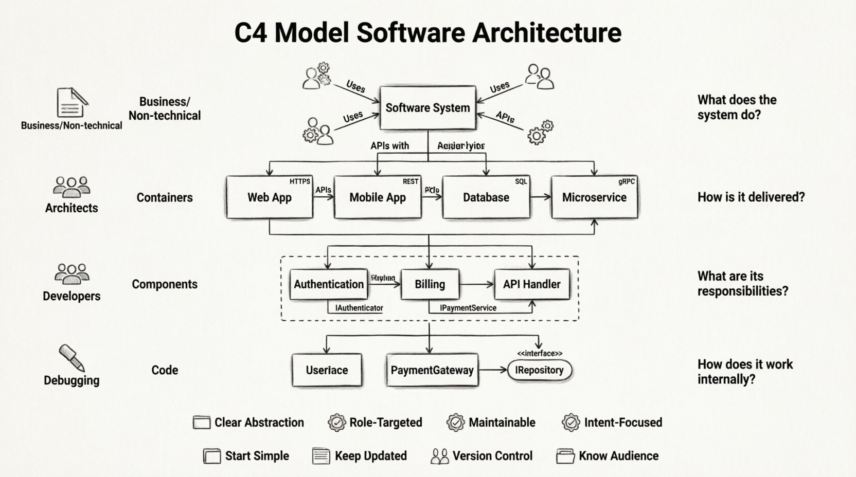
The C4 Model is a collection of diagrams and a hierarchy of abstraction designed to describe software architecture. It was created to address the gap between high-level business requirements and low-level implementation details. The model relies on four levels of abstraction. Each level serves a different audience and answers a specific set of questions. This separation of concerns ensures that stakeholders do not get overwhelmed by unnecessary detail while developers have access to the specifics they need.
- Level 1: System Context (Who uses the system?)
- Level 2: Containers (What are the building blocks?)
- Level 3: Components (How does the logic work?)
- Level 4: Code (What is the internal structure?)
By defining these levels explicitly, teams can maintain a single source of truth. This structure prevents the documentation from becoming a tangled web of interconnected boxes that no one understands. Instead, it creates a clear path for onboarding new team members and planning future refactoring efforts.
🌍 Level 1: System Context Diagrams
The System Context diagram is the most high-level view in the C4 Model. It shows the software system as a single box in the center. Surrounding this box are the people and systems that interact with it. This diagram provides a bird’s-eye view of the ecosystem. It is primarily intended for non-technical stakeholders, new hires, and business analysts.
Key characteristics of a System Context diagram include:
- Single System Box: The software being documented is the only central element.
- External Actors: Users, roles, or other systems that interact with the software.
- Relationships: Lines connecting actors to the system, labeled with the type of data or interaction (e.g., “Stores User Data”, “Sends Notifications”).
- Technology Agnostic: It does not specify the programming language or database type.
When creating this diagram, focus on the boundaries of the system. Do not include internal components. If a user logs in, draw a user icon connecting to the system box. If the system sends emails to a third-party provider, draw that provider as an external system. This clarity helps everyone understand where the responsibility of the system begins and ends.
Common Questions Answered by Level 1
- What is the purpose of this software?
- Who are the main users?
- What external services does it rely on?
- How does it fit into the broader enterprise landscape?
⚙️ Level 2: Container Diagrams
Once the context is established, the next step is to break down the central system box. The Container diagram reveals the high-level building blocks within the system. In software engineering, a container is a deployable unit of software. Examples include web applications, mobile apps, databases, and microservices.
Unlike the system context, this diagram dives into the internal structure of the system itself. It shows how the system is partitioned and how these partitions communicate with one another. This level is crucial for architects and senior developers who need to understand the deployment topology.
Elements found in a Container diagram:
- Containers: Represented as boxes. These are the runtime environments (e.g., a Node.js server, a PostgreSQL database, a React application).
- Connections: Arrows showing data flow between containers. Labels describe the protocol (e.g., HTTP, TCP, SQL).
- Technologies: It is appropriate to mention the technology stack here (e.g., “Java Spring Boot”, “MongoDB”).
This level helps teams visualize the boundaries of microservices. If a system is monolithic, the container diagram might show a single large container. If it is distributed, it will show multiple smaller ones. Understanding these boundaries is vital for understanding scalability and failure points. It also aids in planning infrastructure changes, such as moving a database from on-premise to cloud storage.
Key Decisions at the Container Level
- Should a feature be a separate service or part of the main app?
- What database is appropriate for this specific data type?
- How do services authenticate with each other?
- Are there any legacy components that need migration?
🧩 Level 3: Component Diagrams
The Component diagram drills down further into a single container. It breaks the container into smaller, cohesive units of functionality. A component represents a logical grouping of code, such as a class, module, or package. This level is where the actual business logic starts to become visible.
While the container diagram shows *what* exists, the component diagram explains *how* it works. It is less concerned with the technology stack and more concerned with the responsibilities of the code. This diagram is most useful for developers who are working on specific features or refactoring large modules.
Best practices for Component Diagrams:
- Grouping: Use boxes to group related components together.
- Interfaces: Show how components interact via defined interfaces or APIs.
- Responsibility: Each component should have a clear, single responsibility.
- Abstraction: Do not list every single class. Only show the major functional blocks.
This level helps prevent the “spaghetti code” problem. By visualizing the dependencies between components, developers can see where the coupling is too tight. It encourages modular design. When a new developer joins a project, this diagram serves as a map of the codebase, explaining which module handles authentication and which handles billing.
What This Level Reveals
- How is the business logic organized?
- What are the dependencies between modules?
- Where are the potential bottlenecks in the logic?
- How does data flow through the application logic?
💻 Level 4: Code Diagrams
The final level of the C4 Model is the Code diagram. This is the most detailed view and is generally generated automatically from the source code. It shows classes, interfaces, and methods. While the previous levels are hand-drawn to capture architectural intent, this level is often a snapshot of reality.
Because this level is so granular, it is rarely the primary source of documentation. It is too detailed for most architects. However, it is essential for debugging and understanding specific implementation details. It is best used in conjunction with code comments and inline documentation.
Considerations for Level 4:
- Automation: Use tools to generate these diagrams from code to ensure they are always up to date.
- Scope: Focus on critical paths or complex algorithms.
- Maintenance: These diagrams can become obsolete quickly if code changes frequently.
For most teams, the first three levels are sufficient for high-quality architecture documentation. The fourth level is a safety net for deep dives when necessary.
📊 Comparing C4 with Traditional Approaches
Before adopting a new documentation strategy, it is important to understand how it compares to existing methods. Many teams still rely on UML (Unified Modeling Language) or simple flowcharts. While UML is powerful, it can be overly complex and difficult to maintain for modern software projects.
| Feature | C4 Model | Traditional UML |
|---|---|---|
| Abstraction | Four distinct levels of detail | Often mixes levels, causing confusion |
| Audience | Targeted at specific roles (Business, Dev, QA) | Often generic, confusing for non-technical users |
| Maintainability | Designed to stay relevant as software evolves | Often outdated quickly due to complexity |
| Focus | Software architecture and structure | Can focus on behavior or state machines |
The C4 Model prioritizes simplicity and clarity. It strips away the syntactic complexity of UML in favor of diagrams that communicate intent. This makes it easier for teams to agree on the architecture without getting bogged down in notation rules.
🛠️ Implementation and Maintenance Strategy
Creating the diagrams is only the first step. The real value comes from keeping them up to date. Documentation that is outdated is worse than no documentation at all, as it misleads the team. To ensure longevity, the documentation process must be integrated into the development workflow.
Integrating Documentation into Workflow
- Pull Request Reviews: Require changes to diagrams when architectural changes are proposed.
- Living Document: Treat diagrams as code. Store them in the version control system alongside the source code.
- Automation: Use tools that can generate diagrams from code or configuration files to reduce manual effort.
- Regular Audits: Schedule quarterly reviews to ensure the diagrams match the current state of the software.
By making documentation a part of the definition of done, teams ensure that the system remains understandable. This reduces the “bus factor” risk, where knowledge is held by only one person. When diagrams are part of the repository, any team member can view the architecture at any time.
🚧 Common Pitfalls to Avoid
Even with a solid model like C4, teams can fall into traps that reduce the effectiveness of their documentation. Being aware of these common mistakes helps in steering the process correctly.
- Over-Engineering: Trying to diagram every single class or dependency. This creates noise and reduces readability. Stick to the levels defined in the model.
- Ignoring Audience: Using Level 3 diagrams for business stakeholders. They need Level 1. Using Level 1 for developers is insufficient.
- Static Documentation: Creating the diagrams once and never updating them. This is the quickest way to lose trust in the documentation.
- Tool Obsession: Focusing too much on the tool used to draw the diagram rather than the content. The tool is secondary to the clarity of the message.
- Lack of Standards: Allowing every developer to draw diagrams differently. Establish naming conventions and styling rules early.
🤝 Enhancing Team Communication
Beyond the technical benefits, the C4 Model serves as a communication tool. It provides a shared vocabulary for the team. When an architect says, “We need to change the container boundary,” everyone understands the scope of the change. This shared language reduces ambiguity in meetings and design reviews.
It also facilitates better collaboration between departments. Product managers can look at the System Context diagram to understand how their features fit into the ecosystem. Developers can look at the Component diagram to understand where their code fits. This alignment ensures that everyone is working towards the same architectural goals.
Visualizing the system also helps in risk assessment. When the architecture is visible, it is easier to spot single points of failure. It becomes obvious if a specific container is critical and has no redundancy. This proactive identification of risks allows teams to address them before they become production incidents.
🔮 The Long-Term Value of Architecture Documentation
Investing time in the C4 Model pays dividends over the lifecycle of the software. Projects that grow large without documentation often hit a wall where development slows to a crawl. Engineers spend more time figuring out the code than writing new features. Good architecture documentation removes this friction.
It also aids in onboarding. New hires can review the System Context and Container diagrams to understand the system in days rather than months. This accelerates their ability to contribute meaningfully to the project. In a competitive market, speed of delivery is a key advantage, and documentation supports that speed.
Furthermore, it supports technical debt management. When refactoring is required, the diagrams provide a map of the dependencies. Teams can see what will break if a component is changed. This allows for safer, more confident refactoring efforts. It turns a risky operation into a calculated plan.
📝 Summary of Best Practices
To get the most out of the C4 Model, follow these core principles:
- Start Simple: Begin with the System Context diagram before diving deeper.
- Keep it Updated: Documentation is a living artifact. Update it with every major change.
- Know Your Audience: Match the diagram level to the reader’s needs.
- Focus on Intent: Document the design decisions, not just the current state.
- Use Standard Notation: Stick to the C4 visual conventions for consistency.
- Version Control: Store diagrams alongside your code.
By adhering to these practices, teams can build a robust knowledge base that supports their software for years to come. The C4 Model is not just about drawing boxes; it is about thinking clearly about the system.
🌟 Final Thoughts
The C4 Model represents a shift towards more pragmatic and maintainable software documentation. It bridges the gap between abstract design and concrete code. By adopting this hierarchy, teams can improve communication, reduce risk, and accelerate development. The investment in documentation is an investment in the longevity and health of the software itself.
As software systems continue to grow in complexity, the need for clear, structured documentation becomes more critical. The C4 Model provides the structure needed to navigate this complexity. It is a tool for clarity in a world of chaos. Embracing this model is a step towards building better software systems that stand the test of time.

