


In the fast-paced world of software development, documentation often becomes a casualty of speed. Teams prioritize shipping features over maintaining visual representations of how systems work. Over time, this leads to architecture drift, where the codebase diverges significantly from the original design. Developers spend excessive time reverse-engineering legacy systems, and new joiners struggle to grasp the high-level flow of data. This is where the C4 Model enters the conversation. It offers a structured approach to documenting software architecture that scales with the complexity of the system.
For years, Unified Modeling Language (UML) dominated the landscape of system design. While powerful, standard UML diagrams often proved too verbose or too abstract for modern agile teams. The C4 Model provides a pragmatic middle ground. It focuses on four levels of abstraction, allowing architects to communicate effectively with stakeholders, developers, and operators without drowning them in irrelevant detail. This guide explores whether C4 is the definitive standard for future documentation.
🧩 Understanding the C4 Model Structure
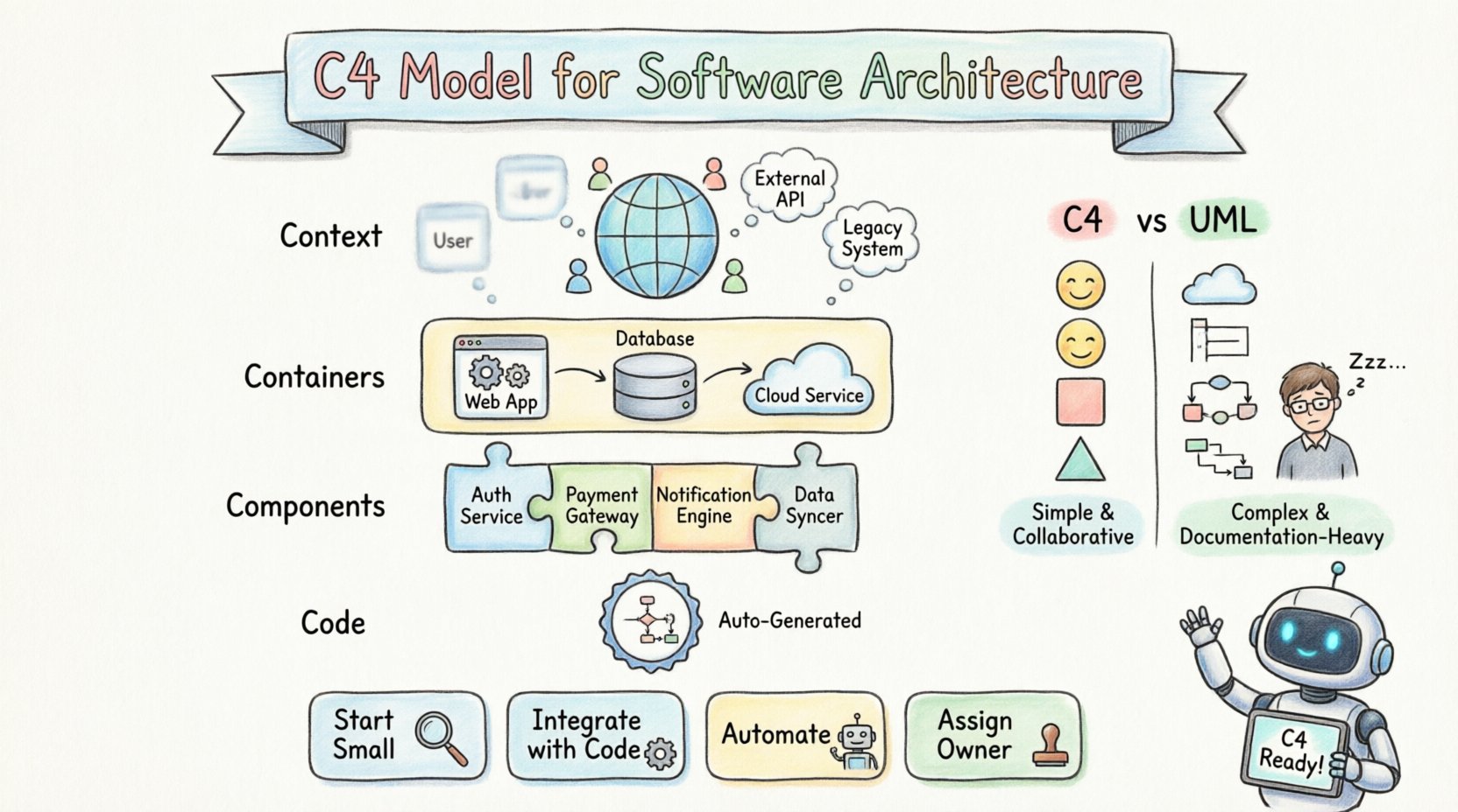
The C4 Model is not a tool, but a conceptual framework. It stands for Context, Containers, Components, and Code. Each level represents a different scope and audience, ensuring that the right people see the right information. The core philosophy is to start high-level and drill down only when necessary. This prevents the common pitfall of creating massive diagrams that no one reads.
- Simplicity: It uses standard shapes to represent boxes and lines, avoiding complex notation.
- Scalability: You can start with a single box and expand as the system grows.
- Human-Centric: It prioritizes understanding over strict mathematical formalism.
Unlike traditional methods that might require a complete redesign every time a minor change occurs, C4 encourages documentation that evolves alongside the code. It acknowledges that perfect documentation is impossible, but useful documentation is achievable.
📊 The Four Levels of Abstraction
The strength of this model lies in its hierarchy. Each level serves a specific purpose and targets a specific group of readers. Understanding these distinctions is crucial for effective implementation.
| Level | Name | Primary Audience | Focus |
|---|---|---|---|
| 1 | System Context | Stakeholders, Managers | High-level boundaries and external systems |
| 2 | Container | Developers, Architects | Deployable units like apps or databases |
| 3 | Component | Developers | Internal structure within a container |
| 4 | Code | Developers | Class-level implementation details |
🔍 Deep Dive: Context Diagrams
The first level is the System Context Diagram. This is the most critical diagram for establishing shared understanding. It answers the question: What is this system, and how does it fit into the wider world?
- The System: Represented as a single box in the center.
- People: External actors interacting with the system.
- Systems: Other software that the system integrates with.
This diagram does not show internal workings. It focuses on data flow and boundaries. For example, a payment service might show connections to a banking API, a user database, and a notification service. This clarity helps stakeholders visualize dependencies without getting bogged down in microservices details.
📦 Deep Dive: Container Diagrams
Once the context is clear, the second level breaks the central system into Containers. A container is a high-level deployable unit. This could be a web application, a mobile app, a database, or a serverless function.
- Technology Agnostic: It describes the purpose, not the specific technology stack.
- Communication: Lines between containers show how they talk (HTTP, gRPC, etc.).
- Boundaries: It defines where the system ends and the infrastructure begins.
For a team building a microservices architecture, this level is vital. It maps out the network topology at an application level. It helps developers understand which parts of the system they need to interact with and which are owned by other teams.
🧱 Deep Dive: Component Diagrams
Inside a container, the system is often too complex to manage. The third level, Components, decomposes a container into smaller, cohesive parts. A component is a logical grouping of functionality.
- Responsibility: Each component has a clear job, like handling authentication or processing orders.
- Interfaces: It defines how other components interact with it.
- Decoupling: It highlights dependencies and separation of concerns.
This level is where most day-to-day development decisions happen. It helps teams identify high coupling or circular dependencies before they become technical debt. It bridges the gap between high-level architecture and actual code structure.
💻 Deep Dive: Code Diagrams
The fourth level is rarely needed for most teams, but it exists for completeness. Code Diagrams show class structures and relationships. In modern object-oriented or functional programming, these diagrams are often generated automatically from the source code.
- Implementation Detail: Shows classes, methods, and attributes.
- Maintenance: Best kept as part of automated documentation tools.
- Usage: Useful for onboarding new developers to a specific codebase.
Most teams skip this level in manual documentation because it changes too frequently. If the code changes, the diagram changes. Relying on code analysis tools for this level is generally more effective than manual drawing.
⚔️ C4 vs. Traditional UML Notation
Why choose C4 over the industry-standard UML? The answer lies in maintenance and cognitive load. UML diagrams are often overly complex, requiring a certification to read and draw correctly. C4 uses standard shapes that anyone can understand.
| Feature | C4 Model | Traditional UML |
|---|---|---|
| Complexity | Low. Standard shapes. | High. Many specific symbols. |
| Maintainability | High. Easy to update. | Low. Hard to keep in sync. |
| Readability | High for non-technical staff. | Low. Technical jargon heavy. |
| Flexibility | Focuses on structure. | Focuses on behavior/state. |
UML excels in describing complex state transitions or behavioral sequences. However, for high-level system architecture, C4 is often more practical. It removes the barrier to entry, allowing architects to focus on design rather than notation rules.
🛠️ Integrating C4 into Your Workflow
Adopting this model requires a shift in mindset. It is not about creating a massive repository of images. It is about creating living documentation that supports the team.
- Start Small: Begin with the System Context diagram. If that is too much, just document the system name and purpose.
- Integrate with Code: Store diagrams in the same repository as the code. This ensures version control and review processes apply to documentation.
- Automate Where Possible: Use tools that generate diagrams from code or configuration files to reduce manual overhead.
- Define Ownership: Assign a specific person or team to maintain the diagrams. Documentation without ownership becomes stale quickly.
The goal is to make documentation a byproduct of development, not a separate task. If a feature changes, the diagram should change as part of the same pull request.
🚧 Navigating Common Implementation Hurdles
Transitioning to this model comes with challenges. Teams often struggle with the initial investment of time and the fear of creating more work.
- Perfectionism: Trying to document every single component leads to burnout. Accept that diagrams will be incomplete.
- Tooling Friction: Manual drawing tools can be slow. Look for solutions that integrate with your existing workflow.
- Resistance to Change: Senior developers may prefer their own mental models. Explain the benefits of shared understanding to overcome this.
- Version Control: Binary diagram files are hard to compare. Use text-based formats for diagrams whenever possible.
It is important to recognize that documentation is a communication tool, not a legal contract. Its value is in the shared mental model it creates between team members. If the diagram helps a developer understand a system faster, it has succeeded.
🤖 The Impact of AI on Diagram Generation
Artificial intelligence is beginning to reshape how we create architecture documentation. AI tools can analyze codebases and suggest component structures. This reduces the manual effort required to keep diagrams up to date.
- Automated Extraction: AI can parse code repositories to identify boundaries and dependencies.
- Suggestion Engines: Tools can recommend where a container fits in the system context.
- Change Detection: AI can flag when the code deviates from the documented architecture.
While AI is powerful, it cannot replace human judgment. An architect must still decide what is important to show and what to hide. AI handles the mechanics; humans handle the strategy.
🔄 Keeping Documentation Alive
The biggest enemy of architecture documentation is time. Systems evolve, and old diagrams become misleading. To combat this, teams must adopt a culture of documentation hygiene.
- Review Cycles: Schedule regular reviews of diagrams during sprint planning or retrospectives.
- Onboarding: Use the diagrams as part of the onboarding process for new hires. If they are useful for learning, they are useful for the team.
- Minimal Viable Documentation: Focus on the 20% of diagrams that provide 80% of the value. Ignore the rest.
By treating diagrams as code, teams can apply the same rigor to their documentation. This includes code reviews, automated testing of diagram consistency, and continuous integration pipelines that verify the diagrams match the code.
📈 The Long-Term Value of Structure
Investing in clear architecture documentation pays dividends over the lifecycle of a project. It reduces the cost of change. When you know how the pieces fit together, you can modify them with less fear of breaking dependencies.
- Reduced Cognitive Load: New developers spend less time asking questions.
- Faster Onboarding: Visual aids accelerate the learning curve.
- Better Communication: Stakeholders get a clear picture without technical jargon.
- Improved Decision Making: Architecture decisions are recorded and explained.
The choice to adopt this model is not about following a trend. It is about recognizing that software is a communication medium. The code communicates with the machine, but the diagrams communicate with the people building and maintaining the code. As systems grow in complexity, the need for clear, structured communication becomes critical.
Whether C4 becomes the universal standard is less important than whether it solves the specific problems your team faces. If it helps you build better systems and understand them better, it has done its job. The future of architecture documentation lies in tools and practices that reduce the friction of keeping information current. Models that prioritize clarity over complexity will naturally rise to the top.

