


The landscape of software architecture documentation often resembles a maze without a map. Teams build systems, update code, and shift strategies, yet the visual documentation frequently lags behind. This disconnect creates friction. It slows down onboarding, confuses stakeholders, and introduces technical debt in the form of misunderstood systems. The C4 Model offers a solution by providing a structured hierarchy of diagrams. It moves from the broadest context down to the finest details of code.
However, simply creating diagrams is not enough. The true value lies in consistency. When every diagram tells the same story using the same visual language, communication becomes efficient. This guide provides a comprehensive checklist for maintaining that consistency across the C4 Model levels. We will explore the specific requirements for Context, Containers, Components, and Code diagrams, ensuring your documentation remains a reliable asset rather than a source of confusion.
🔍 Why Consistency Matters in Architecture Documentation
Consistency is not merely an aesthetic preference; it is a functional requirement. When stakeholders review architecture diagrams, they rely on patterns to interpret information quickly. If the icon for a user changes between the System Context diagram and the Container diagram, the reader must stop and re-learn the visual language. This cognitive load slows down decision-making. Consistency ensures that the focus remains on the architecture itself, not the symbols used to represent it.
Furthermore, consistency supports maintenance. In large organizations, multiple teams contribute to the same documentation. Without a shared standard, the documentation fragments. One team might use a database icon for a service, while another uses a server icon for the same concept. A unified standard prevents this fragmentation and ensures that the documentation remains accurate over time.
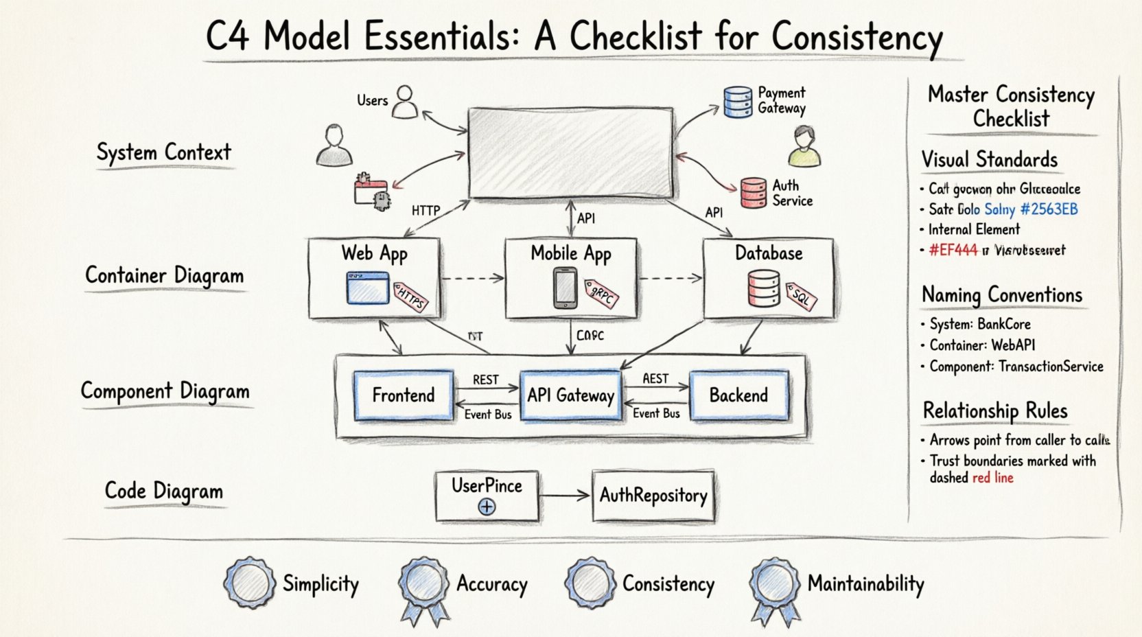
🌍 Level 1: System Context Diagrams
The System Context diagram defines the boundaries of the system in question. It shows the system as a single box and the people or systems that interact with it. This level is the entry point for understanding the software ecosystem.
📌 Consistency Rules for Context Diagrams
- System Naming: Always use the official product name for the central box. Do not abbreviate unless the abbreviation is industry-standard.
- External Systems: Represent external dependencies clearly. Use standard icons for common types of systems, such as public APIs, third-party services, or legacy databases.
- Users: Distinguish between different types of users. For example, an internal administrator is different from an external customer. Use consistent icons for these personas across all diagrams.
- Relationships: Label the data flowing between the system and external actors. Ensure the direction of the arrow indicates the flow of data, not just a connection.
When drawing these diagrams, maintain a clear separation between the system and its environment. Do not draw internal components here. The focus is strictly on the perimeter. If a dependency changes, update the diagram immediately. Stale dependencies mislead developers about what is actually required to run the system.
📦 Level 2: Container Diagrams
The Container diagram zooms in to show the high-level technical building blocks. A container is a deployable unit, such as a web application, a mobile app, a database, or a serverless function. This level answers the question: “What technologies are we using?”
📌 Consistency Rules for Container Diagrams
- Technology Icons: Select a consistent set of icons for technology types. For instance, always use the same icon for a SQL database and the same icon for a NoSQL database across all diagrams.
- Deployment Boundaries: Clearly indicate which containers reside on the same server or cloud instance. Use a dashed boundary box if necessary to show a physical or logical grouping.
- Communication Protocols: Label the protocols used between containers. Common protocols include HTTP, HTTPS, gRPC, or AMQP. Do not assume the reader knows the default protocol.
- Responsibility Labels: Each container should have a short description of its primary responsibility. This prevents ambiguity about why a specific service exists.
| Element | Consistency Guideline | Why It Matters |
|---|---|---|
| Container Icon | Use standard technology icons | Reduces cognitive load when identifying tech stack |
| Data Flow | Label all arrows with protocol names | Clarifies security and performance requirements |
| Naming | Use fully qualified domain names or service names | Matches infrastructure configuration files |
At this level, avoid showing internal logic. If a container has multiple services, show them as separate containers if they are deployable independently. If they run together as a monolith, group them under a single container boundary. The goal is to map the runtime architecture accurately.
🧩 Level 3: Component Diagrams
The Component diagram reveals the internal structure of a container. It breaks down the container into logical components that work together. A component is a cohesive unit of code, such as a module, a package, or a library. This level is critical for developers who need to understand how the code is organized.
📌 Consistency Rules for Component Diagrams
- Component Boundaries: Ensure that components do not overlap. A component should have a single responsibility. If a box represents multiple responsibilities, split it into two components.
- Interfaces: Define how components interact. Use open-ended arrows to show provided interfaces and closed arrows for consumed interfaces. This visualizes the contract between parts.
- Internal Data Stores: If a component contains a database or file store, represent it explicitly. Do not hide data persistence inside a generic component box without indication.
- Dependency Direction: Arrows should point from the consumer to the provider. This indicates who depends on whom, which is vital for understanding coupling.
Consistency at this level is often the hardest to maintain. Code evolves faster than diagrams. To keep up, align the diagram structure with the code repository structure. If the code is organized by feature, the diagram should reflect feature boundaries. If the code is organized by layer, the diagram should reflect layer boundaries. This alignment makes the diagram a true reflection of the codebase.
🖥️ Level 4: Code Diagrams
The Code diagram is the most detailed level. It shows the internal structure of a component, often mapping to classes, interfaces, and methods. This level is rarely needed for high-level architecture but is essential for complex algorithms or critical interfaces.
📌 Consistency Rules for Code Diagrams
- Granularity: Do not diagram every single method. Focus on the public API of the component. Show the classes that define the contract.
- Visibility: Use standard visibility symbols (+ for public, – for private). This is a universal standard in object-oriented design.
- Relationships: Clearly distinguish between inheritance, implementation, and association. Use standard UML symbols for these relationships to maintain industry standard compliance.
Because this level is highly technical, it is often best kept in the code repository itself. If you choose to maintain it as a standalone diagram, ensure it is generated from the code automatically if possible. Manual updates to code diagrams are prone to becoming outdated very quickly.
🛠️ The Master Consistency Checklist
To ensure your documentation remains useful, apply this checklist to every diagram you create or update. This list covers visual standards, naming conventions, and relationship rules.
📝 Visual Standards
- ✅ Are all icons from the same library or set?
- ✅ Are colors used consistently to represent status or type (e.g., red for external, blue for internal)?
- ✅ Is the font size and type uniform across all diagrams?
- ✅ Are line widths and arrowheads consistent?
📝 Naming Conventions
- ✅ Are system names consistent with the project repository name?
- ✅ Are container names consistent with the deployment configuration?
- ✅ Are component names descriptive and free of jargon?
- ✅ Are labels on relationships clear and concise?
📝 Relationship Rules
- ✅ Do all arrows indicate data flow direction?
- ✅ Are protocols labeled on the connection lines?
- ✅ Are trust boundaries clearly marked where sensitive data crosses?
- ✅ Is the diagram updated whenever a dependency changes?
⚠️ Common Pitfalls in C4 Documentation
Even with a checklist, teams often fall into traps that degrade the quality of their documentation. Being aware of these pitfalls helps you avoid them.
🚫 Over-Engineering the Diagram
One common mistake is trying to show too much detail in a single diagram. A System Context diagram should not contain component details. A Container diagram should not contain class details. Each level has a specific purpose. Mixing levels confuses the reader. Keep the abstraction level appropriate for the audience.
🚫 Ignoring the Audience
Diagrams serve different people. Executives need high-level context. Developers need container and component details. Do not try to make one diagram satisfy everyone. Create a set of diagrams tailored to specific roles. If you force a single diagram to serve all purposes, it will likely fail to serve any purpose effectively.
🚫 Static Documentation
Documentation that is never updated is worse than no documentation. It creates a false sense of security. Treat diagrams as living documents. Integrate diagram updates into the definition of done for software tasks. If a pull request changes the architecture, the diagram must be updated in the same commit.
🔄 Maintenance and Evolution
Architecture documentation is not a one-time task. Systems evolve, and so must the diagrams. Establish a routine for reviewing the C4 diagrams. A quarterly review is often sufficient for stable systems, but high-churn systems may need monthly checks.
Consider automating parts of the process. Many diagramming tools allow you to generate diagrams from code or configuration files. While manual drawing offers flexibility, automation ensures accuracy. If you use a tool that supports code generation, prioritize it for the lower levels (Components and Code). Use manual drawing for the higher levels (Context and Containers) where business logic and external relationships are more important than technical implementation.
Training is also a key component of consistency. New team members should learn the C4 standards during their onboarding. Provide them with a style guide that defines the icon set, color palette, and naming conventions. This ensures that everyone contributes to the documentation in the same way.
📊 Summary of Best Practices
Maintaining consistency in the C4 Model requires discipline and a clear set of rules. By adhering to the checklist provided, teams can create documentation that is accurate, readable, and maintainable. The key is to treat the diagrams as part of the codebase, not as an afterthought.
Remember the core principles:
- Simplicity: Keep diagrams clear and uncluttered.
- Accuracy: Ensure diagrams match the actual system state.
- Consistency: Use the same symbols and conventions everywhere.
- Maintainability: Update diagrams alongside code changes.
When these principles are followed, the C4 Model becomes more than just a drawing standard. It becomes a communication tool that aligns the entire organization on how the software works. This alignment reduces errors, speeds up development, and creates a stronger foundation for future growth.

