


Sequence diagrams are a fundamental component of system design documentation. They illustrate how objects interact over time, providing a clear visual representation of workflow logic. Understanding sequence diagram notation is essential for architects, developers, and stakeholders to communicate complex system behaviors without ambiguity. This guide covers the syntax, semantics, and best practices for creating effective interaction diagrams.
🧩 Understanding the Basics
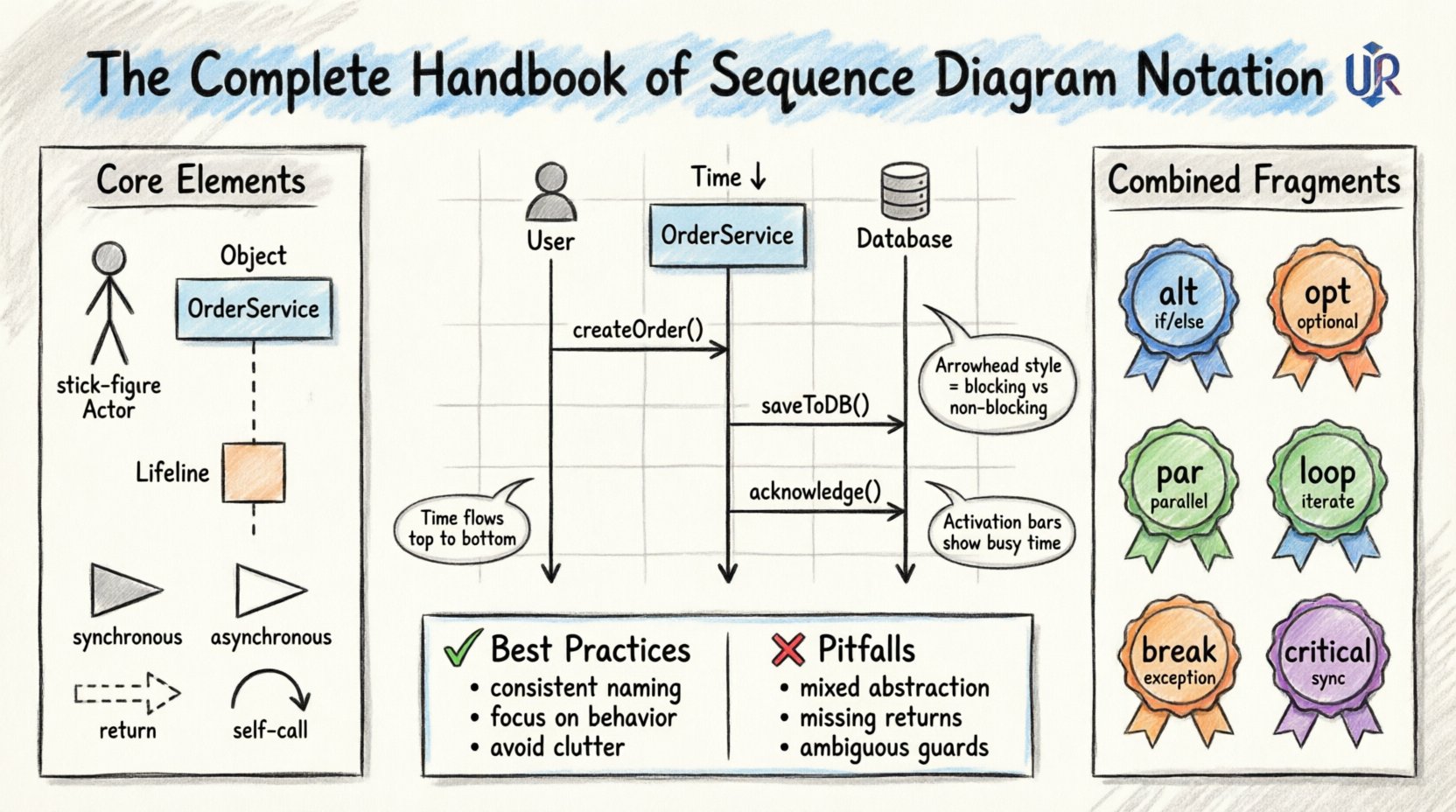
A sequence diagram maps out the interactions between participants in a specific scenario. Time flows from top to bottom. The horizontal axis represents different participants, while the vertical axis represents the passage of time. The notation relies on a standardized set of symbols defined by the Object Management Group (OMG) for Unified Modeling Language (UML).
Key characteristics include:
- Time Order: Messages appear in chronological order.
- Participants: Entities involved in the interaction (objects, actors, systems).
- Messages: Signals passed between participants to trigger behavior.
- Lifelines: The vertical dashed lines indicating the existence of a participant over time.
🏗️ Core Notation Elements
Before diving into complex logic, one must master the foundational symbols. Each element serves a specific purpose in defining the lifecycle and communication of system components.
1. Lifelines and Participants
A lifeline represents a single instance of a participant. It is drawn as a vertical dashed line extending from the top of the diagram. At the top of the line sits a rectangle containing the name of the object or actor. This rectangle anchors the lifeline and identifies the entity.
- Actor: Represented by a stick figure icon. Usually denotes a human user or an external system.
- Object: Represented by a rectangle with the object name, often italicized (e.g., OrderProcessor).
- System Boundary: Sometimes used to group multiple objects belonging to a specific subsystem.
2. Activation Bars
Activation bars (or focus of control) are thin rectangles placed on the lifeline. They indicate the period during which an object is actively performing an operation. When a message is received, the activation bar begins. It ends when the operation completes or returns control to the caller.
- Execution Control: Shows when an object is busy processing.
- Stack Depth: Multiple activation bars can stack to show nested calls.
- Visibility: Helps identify bottlenecks where an object waits for a long duration.
3. Message Arrows
Messages connect lifelines horizontally. The arrow style defines the communication mechanism. The standard types include:
- Synchronous Call: Solid line with a filled arrowhead. The sender waits for the receiver to finish.
- Asynchronous Call: Solid line with an open arrowhead. The sender does not wait.
- Return Message: Dashed line with an open arrowhead. Indicates a response or data return.
- Self-Call: An arrow that starts and ends on the same lifeline. Used for internal method calls.
⚙️ Advanced Logic and Combined Fragments
Real-world systems rarely follow a single linear path. Combined fragments allow for conditional logic, loops, and parallel processing within the diagram. These are enclosed in a rectangle with a label in the top-left corner.
Table: Common Combined Fragment Operators
| Operator | Symbol | Purpose |
|---|---|---|
| alt | alt | Alternative paths (if/else logic). |
| opt | opt | Optional path (if present). |
| loop | loop | Iterative process (for each item). |
| par | par | Parallel execution (concurrent threads). |
| break | break | Exception handling (abort flow). |
| critical | critical | Resource locking (synchronization). |
1. Alternative (alt)
The alt fragment splits the interaction into distinct sections based on a condition. Each section is separated by a horizontal dashed line. Only one section executes based on the evaluation of the boolean guard condition.
- Use Case: Validating user input where success and failure paths differ.
- Structure: Condition 1 | Condition 2 | else.
2. Optional (opt)
The opt fragment represents a single path that may or may not occur. It is useful for optional features or non-blocking operations.
- Use Case: Sending a notification email only if the user has opted in.
- Structure: [Condition: User has permission].
3. Loop
The loop fragment indicates that the enclosed messages repeat. The condition usually specifies the iteration count or termination criteria.
- Use Case: Processing a list of items from a database.
- Structure: [while (items.hasNext())].
4. Parallel (par)
The par fragment shows that multiple messages happen simultaneously. This is common in multi-threaded environments or microservices communicating via event buses.
- Use Case: Saving a record to the database while simultaneously logging the event.
- Structure: [parallel].
🛠️ Object Lifecycle Management
Objects are created and destroyed dynamically during system execution. Sequence diagrams capture these transitions to show the lifecycle of components.
Object Creation
When a new instance is generated, a special message is sent to the target lifeline. The arrowhead is a solid line with a thick block, and the target lifeline starts at the point of creation.
- Constructor Call: Indicates the initialization of a new object.
- Factory Method: Often used to abstract the creation logic.
Object Destruction
When an object is no longer needed, it is destroyed. This is depicted by an ‘X’ mark on the lifeline. The activation bar ends at this point.
- Garbage Collection: Marks the end of scope for local variables.
- Transaction Rollback: Indicates cleanup of temporary resources.
📏 Best Practices for Notation
Creating a diagram is not just about drawing lines; it is about communicating intent clearly. Adhering to standards ensures that any developer can read the documentation without confusion.
1. Consistency in Naming
Use consistent naming conventions for messages and objects. If an object is named OrderService in the class diagram, it should be named OrderService in the sequence diagram. Message names should reflect the method or action being performed.
- Verb-Noun: Use
getOrderDetails()rather thanFetch Info. - Scope: Prefix messages with the object name if context is unclear.
2. Focus on Behavior
Sequence diagrams describe behavior, not structure. Avoid showing database tables or file system paths unless they are critical to the logic flow. Keep the focus on the interaction between software components.
- Abstraction: Treat databases as black boxes unless the query logic is the point of the diagram.
- State Changes: Do not attempt to show every state variable change; focus on the triggers.
3. Avoid Clutter
A crowded diagram is a useless diagram. If a sequence diagram becomes too complex, break it down into smaller sub-diagrams using call frames.
- Call Frame: Encapsulate a complex interaction as a single message box.
- Refinement: Create a separate diagram for the called interaction.
4. Limit the Scope
Do not attempt to document the entire system in one diagram. Focus on specific use cases or critical flows. A diagram should answer a specific question, such as “How is a payment processed?” rather than “How does the system work?”.
🚫 Common Pitfalls to Avoid
Even experienced practitioners can introduce ambiguity. Be mindful of these common errors that degrade the quality of the documentation.
- Mixing Levels of Abstraction: Do not show high-level API calls alongside low-level database queries in the same flow. It confuses the reader about the architectural layers.
- Ignoring Return Messages: Forgetting to show return messages makes the diagram look incomplete and hides data flow.
- Overusing Loops: Placing a loop around a large section can make the diagram hard to read. Consider using a call frame for the loop body instead.
- Ambiguous Guards: Writing “if error” instead of “if error code is 500” reduces precision.
- Disconnected Lifelines: Ensure all participants are connected logically. A lifeline that appears but has no messages is likely unnecessary.
📝 Documentation Strategy
Sequence diagrams are part of a larger documentation ecosystem. They should complement class diagrams, state diagrams, and activity diagrams.
Integration with Class Diagrams
The participants in a sequence diagram should correspond to classes in the class diagram. If a participant does not exist in the class diagram, the sequence diagram is defining a new dependency that needs to be modeled structurally.
Integration with State Diagrams
While sequence diagrams show interaction over time, state diagrams show how a single object changes state. Use sequence diagrams for system flow and state diagrams for complex object logic.
🔄 Maintenance and Evolution
Documentation is not a one-time task. As the system evolves, the diagrams must be updated. A diagram that does not match the current code is worse than no diagram at all.
- Version Control: Treat diagrams as code. Store them in version control systems.
- Review Process: Include diagram updates in code review pull requests.
- Automation: Where possible, generate diagrams from code annotations to reduce drift between implementation and documentation.
🎨 Visual Styling and Readability
While color and style do not change the semantics of the notation, they significantly impact readability. Use visual cues to distinguish between different types of components.
- Color Coding: Assign a color to external systems (e.g., gray) and internal services (e.g., blue).
- Font Weight: Use bold text for critical messages or high-priority actors.
- Alignment: Ensure message arrows are aligned neatly. Crooked lines suggest disorder.
🔍 Deep Dive: Asynchronous Communication
Understanding asynchronous messaging is crucial for modern distributed systems. In an asynchronous call, the sender initiates the message and continues execution immediately. The receiver processes the message in the background.
Characteristics:
- Fire and Forget: The sender does not wait for a response.
- Decoupling: Reduces dependency between sender and receiver.
- Event Driven: Commonly used in event-driven architectures.
In notation, this is represented by a solid line with an open arrowhead. It is important to note that while the sender does not wait, the receiver still has a lifeline and activation bar to process the incoming task.
🔍 Deep Dive: Synchronous Communication
Synchronous communication implies a blocking call. The sender pauses execution until the receiver returns a result. This is the default assumption for most method calls in object-oriented programming.
Characteristics:
- Blocking: Execution stops at the call point.
- Dependency: The sender depends on the immediate result.
- Response Required: A return message must follow the call.
In notation, this is a solid line with a filled arrowhead. The activation bar of the sender extends until the return message is received, visually representing the wait time.
🧠 Summary of Notation Semantics
Mastering sequence diagram notation requires understanding both the syntax and the intent behind each symbol. The following points summarize the core takeaways:
- Time is Vertical: Top to bottom indicates progression.
- Participants are Horizontal: Side to side indicates distinct entities.
- Arrows define Flow: Arrowhead style defines blocking vs. non-blocking.
- Frames define Logic:
alt,loop, andpardefine control structures. - Activation defines Work: Bars show when an object is busy.
By adhering to these standards, teams can ensure that their design documentation remains clear, maintainable, and valuable throughout the software development lifecycle.
