


Creating accurate sequence diagrams is a fundamental skill for software architects and system analysts. These visual artifacts map out the interactions between objects or components over time. However, as systems grow in complexity, the diagrams often become difficult to read or misleading. Poorly designed diagrams can lead to miscommunication between development teams, errors in implementation, and significant technical debt. This guide explores the common pitfalls encountered during the design process and provides actionable strategies to maintain clarity and precision.
When constructing these models, the goal is not merely to depict what happens, but to clarify how the system behaves under various conditions. Ambiguity in message flow, incorrect lifeline management, or excessive nesting can obscure the true logic of the application. By understanding the structural requirements and adhering to best practices, you can create documentation that serves as a reliable source of truth throughout the software development lifecycle.
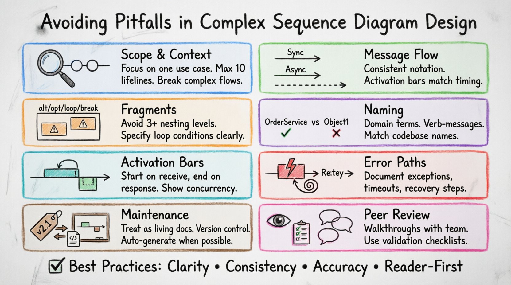
1. Defining the Scope and Context 🎯
One of the most frequent errors is attempting to capture the entire system behavior in a single diagram. Sequence diagrams are designed to illustrate specific interactions, not the complete state of an application. When the scope is too broad, the diagram becomes cluttered with irrelevant messages, making it hard to identify the critical path.
- Over-Engineering: Including every possible API call or internal method invocation.
- Missing Context: Failing to define the initial trigger or the expected outcome.
- Boundary Confusion: Blurring the line between internal processing and external system calls.
To avoid these issues, start by defining the specific use case or scenario you are documenting. Focus on the primary flow and the critical exceptions. If a diagram requires more than ten lifelines or spans dozens of message exchanges, it is likely too complex for a single view. Consider breaking the process into multiple diagrams, each focusing on a distinct aspect of the interaction.
2. Message Flow and Interaction Types 📡
The direction and type of messages sent between objects convey the logic of the system. Misusing synchronous versus asynchronous messages can misrepresent the execution flow. A synchronous message implies a blocking call where the sender waits for a response. An asynchronous message indicates fire-and-forget behavior, where the sender continues processing without waiting.
- Synchronous Calls: Represented by solid lines with filled arrowheads. The sender waits for the receiver to complete the task.
- Asynchronous Calls: Represented by solid lines with open arrowheads. The sender does not wait for a return signal.
- Return Messages: Represented by dashed lines. These are often omitted for brevity but are crucial for understanding the full response cycle.
Consistency is key. If you use solid lines for blocking calls in one section, do not switch to dashed lines for the same type of interaction in another. Ensure that the timing of the activation bars aligns with the message flow. A receiver should not show an activation bar before the message arrives, and it should end when the response is sent or the task is complete.
3. Managing Complexity with Fragments 🧩
Complex logic often requires conditional branching or loops. Sequence diagrams use fragments to represent these structures. The standard fragments include alt (alternative), opt (optional), loop, and break. While powerful, overusing these fragments can create a visual maze that is difficult to follow.
Excessive nesting of fragments is a common source of confusion. If you find yourself nesting three or more levels of alt blocks, the logic is likely too complex for this format. It is better to split the logic into separate diagrams or use a different modeling technique for that specific section.
| Pitfall | Consequence | Solution |
|---|---|---|
| Deep Nesting | Visual clutter, hard to trace paths | Split into multiple diagrams |
| Vague Conditions | Unclear decision criteria | Use precise boolean expressions |
| Missing Alternatives | Incomplete logic coverage | Ensure all branches are represented |
| Inconsistent Labels | Confusion during review | Standardize fragment naming |
When using the loop fragment, specify the iteration condition clearly. If the loop represents a batch process, indicate the range or the termination condition. Do not assume the reader can infer the number of iterations from the context alone. Explicit is always better than implicit in technical documentation.
4. Naming Conventions and Clarity 🏷️
Readability depends heavily on the names used for participants and messages. Generic names like Object1, ComponentA, or Process provide no context. They force the reader to rely on external documentation to understand what the diagram represents. In the absence of clear labels, the diagram loses its value as a standalone reference.
- Use Domain Terminology: Align names with the business domain. If the system handles orders, use
OrderServiceinstead ofManager. - Verb-Based Messages: Message names should describe the action, such as
calculateTotalorvalidateUser. - Consistent Capitalization: Stick to a style guide, such as PascalCase for classes and camelCase for methods.
- Avoid Abbreviations: Unless they are universally understood, spell out terms to prevent ambiguity.
When lifelines represent classes or interfaces, ensure the names match the codebase. This alignment reduces the cognitive load during code reviews and helps developers verify that the implementation matches the design. Discrepancies between diagram labels and code identifiers can lead to implementation errors.
5. Lifecycle and Activation Bars ⏱️
Activation bars indicate the period during which an object is actively performing an action. Incorrect placement of these bars can mislead readers about the duration of processes or the state of the object. An activation bar should start when a message is received and end when the response is sent or the control returns to the caller.
- Self-Messages: When an object calls itself, the activation bar must remain continuous or be split appropriately to show the recursive nature.
- Parallel Processing: If a system spawns multiple threads or processes, activation bars should reflect the concurrent execution rather than a linear sequence.
- Long-Running Tasks: If a process takes significant time, consider indicating a delay or breaking the activation into logical steps.
It is also important to manage nested objects correctly. When an object is created dynamically within the flow, it should appear on the lifeline only after the creation message. Do not show the object at the top of the diagram if it is instantiated during the interaction. This visual distinction helps clarify the initialization sequence.
6. Handling Exceptions and Error Paths ⚠️
Happy path diagrams show the ideal scenario, but real-world systems must handle errors. Ignoring exception handling in sequence diagrams creates a false sense of security. Developers may assume the system never fails, leading to inadequate error handling in the code.
- Exception Fragments: Use
exceptionorbreakfragments to show error paths. - Recovery Steps: Indicate how the system recovers from a failure, such as retrying a transaction or notifying a user.
- Timeouts: Represent network timeouts or resource exhaustion clearly.
- Rollbacks: Show the cleanup process when a transaction is aborted.
By documenting error paths, you ensure that the resilience of the system is understood by all stakeholders. This is particularly important for distributed systems where network failures are common. A diagram that only shows successful communication is incomplete.
7. Maintenance and Diagram Drift 🔄
One of the most persistent challenges in software engineering is keeping documentation in sync with the code. As features change, diagrams often become outdated. This drift renders the documentation useless and can mislead new team members. To mitigate this, treat diagrams as living documents that require version control.
- Automated Generation: Where possible, generate diagrams from code annotations to ensure accuracy.
- Review Triggers: Update diagrams as part of the code review process for significant changes.
- Versioning: Tag diagrams with the corresponding software version or commit hash.
- Deprecation: Mark old diagrams as obsolete rather than deleting them, allowing for historical reference.
Regular audits of the documentation against the current codebase can prevent major discrepancies. If a diagram cannot be updated without significant effort, consider it a sign that the system design is too complex to document effectively in that format.
8. Validation and Peer Review 👁️
Before finalizing a sequence diagram, it should undergo a review by peers who are not the primary author. Fresh eyes can spot logical gaps, inconsistent naming, or unclear flows that the author may have overlooked. This process ensures that the diagram communicates effectively to the intended audience.
- Walkthroughs: Conduct a step-by-step walkthrough with stakeholders to validate the flow.
- Checklists: Use a checklist to verify common elements like message types, lifelines, and fragments.
- Feedback Loops: Encourage constructive criticism to improve clarity and accuracy.
Validation is not just about correctness; it is about usability. If a diagram requires a legend to explain the symbols, the design may be too abstract. The goal is to create a visual language that is intuitive to those familiar with the system architecture.
Summary of Best Practices
Adhering to these guidelines ensures that your sequence diagrams remain valuable assets throughout the project lifecycle. Focus on clarity, consistency, and accuracy. Avoid the temptation to show everything at once. Break down complex interactions into manageable units. Maintain alignment with the codebase. And always prioritize the reader’s ability to understand the system behavior.
By addressing these common pitfalls, you contribute to a more robust software architecture process. Clear diagrams reduce ambiguity, facilitate better communication, and ultimately lead to higher quality software delivery.

