


Understanding the flow of interactions within a complex software system is critical for architects, developers, and testers. A sequence diagram serves as a visual narrative that maps out how objects or participants communicate over time. While the concept seems straightforward, the notation contains specific symbols and rules that define the behavior of the system. This guide provides a detailed breakdown of every component, ensuring you can interpret these diagrams with precision and clarity.
Whether you are reviewing legacy code or designing a new microservice architecture, the ability to decode these diagrams translates directly to better system reliability and maintainability. We will explore the visual elements, the logic behind the flow, and the nuances that often get overlooked during a quick review.
Core Participants: Lifelines and Actors 👥
The foundation of any sequence diagram is the participant. These represent the entities involved in the interaction. They are the static elements that facilitate the dynamic behavior shown in the diagram.
1. Lifelines
A lifeline is the vertical dashed line extending downward from a participant. It represents the existence of that object or actor over time. Here is what you need to know about lifelines:
- Identity: The top of the lifeline contains a rectangle with the name of the object or class.
- Time Axis: Time flows from top to bottom along this line. Events occurring lower down happen later in the process.
- Scope: A lifeline exists for the duration of the interaction being modeled. If an object is created during the process, the lifeline may start partway down.
- State: While the line itself is static, the object’s state changes as messages are received and processed.
2. Actors
Actors represent external entities that initiate or receive information from the system. They are typically drawn as stick figures.
- Human Users: A customer logging in or an administrator configuring settings.
- External Systems: A third-party payment gateway or an API from another service.
- Triggers: Actors often start the sequence by sending the first message to the system.
3. Objects and Classes
Internal components are represented as rectangles. These are the software units handling the logic.
- Instance Names: Often written as objectName:ClassName (e.g., cart:ShoppingCart).
- Roles: A single class might play different roles in different parts of the diagram, indicated by different instance names.
- Grouping: Related objects can be grouped within a frame to show a specific context or subsystem.
The Flow: Messages and Communication 📨
Messages are the horizontal arrows connecting lifelines. They represent the transfer of information or the invocation of behavior. The type of arrow indicates the nature of the communication.
1. Synchronous Calls
This is the most common message type. The sender waits for the receiver to finish the operation before continuing.
- Visual: A solid line with a filled arrowhead.
- Behavior: The sender’s execution is suspended until the response returns.
- Use Case: Retrieving a user profile, calculating a tax, or saving a database record.
2. Asynchronous Messages
The sender does not wait for the response. It sends the message and continues its own processing immediately.
- Visual: A solid line with an open (hollow) arrowhead.
- Behavior: Fire-and-forget. No immediate blocking occurs.
- Use Case: Sending a notification, logging an event, or triggering a background job.
3. Return Messages
Responses from the receiver back to the sender complete the interaction loop.
- Visual: A dashed line with an open arrowhead.
- Direction: Points back up towards the original caller.
- Implied Returns: In some notations, return messages are omitted if the context is clear, but explicit returns are preferred for clarity in complex flows.
4. Create and Destroy Messages
Objects are not always static. They can be instantiated or terminated during the sequence.
- Creation: Represented by a message ending with a special “new” symbol or a specific arrow type. A new lifeline appears further down the diagram.
- Destruction: Represented by an
Xat the bottom of a lifeline. This indicates the object is no longer active or valid.
Focus of Control: Activation Bars 🔋
Activation bars (also known as method bars or execution occurrences) are narrow rectangles placed on top of a lifeline. They indicate when the object is actively performing an action.
What the Activation Bar Tells You
- Duration: The length of the bar represents the time the object is busy processing.
- Reentrancy: If an object calls itself (recursive), a new activation bar will appear inside the existing one.
- Concurrency: If a message is asynchronous, the activation bar might continue while the sender moves on, indicating parallel execution.
Why It Matters
Ignoring activation bars can lead to performance bottlenecks. If a bar is excessively long, it suggests a heavy computation or a blocking I/O operation. This is a primary indicator for optimization opportunities in system design.
Control Structures: Fragments and Loops 🔄
Not every interaction follows a straight line. Real-world logic involves conditions, repetitions, and optional paths. These are handled using fragments.
1. Alt (Alternative)
Used to represent conditional logic, similar to an if-else statement.
- Structure: A frame box labeled
altcontaining multiple operands separated by horizontal lines. - Guards: Each operand has a condition (e.g.,
[user is valid]). - Execution: Only one operand is executed based on the condition being true.
2. Opt (Optional)
Used when a part of the sequence might not happen at all.
- Structure: A frame labeled
opt. - Logic: If the guard is true, the interaction occurs. If false, it is skipped entirely.
- Use Case: Showing a “Remember Me” checkbox or an optional discount code.
3. Loop
Represents repetitive actions.
- Structure: A frame labeled
loop. - Iteration: Can specify a count (e.g.,
[1 to 10]) or a condition (e.g.,[while items exist]). - Use Case: Processing a list of orders, iterating through a database result set.
4. Break
Indicates that the loop or fragment can be terminated early.
- Logic: Used when an error occurs or a specific condition is met that stops the iteration.
Timing and Order ⏱️
Sequence diagrams primarily show logical order, but timing can be implied or explicitly stated.
1. Strict Ordering
Messages are drawn from left to right and top to bottom. A message sent from Line A before Line B implies A happens first.
2. Parallelism
Some diagrams show multiple messages sent from a single lifeline simultaneously. This indicates concurrent processing.
- Visual: Multiple arrows originating from the same activation bar at the same vertical level.
- Implication: The system is utilizing multiple threads or processes.
3. Time Constraints
While not always present, specific time limits can be noted.
- Labels: Text like
[timeout: 5s]attached to a message or frame. - Relevance: Critical for real-time systems where delays cause failure.
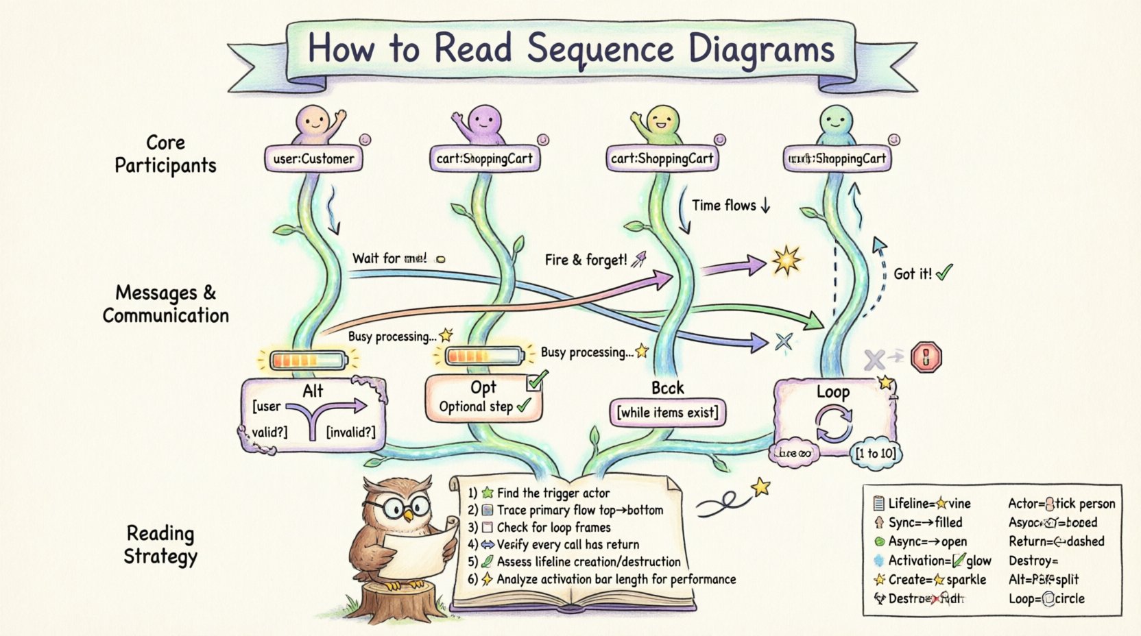
Reading Strategy: A Step-by-Step Analysis 📝
Reading a sequence diagram effectively requires a structured approach. Do not just look at the arrows; analyze the lifecycle of the data.
- Identify the Trigger: Find the actor or system that starts the process. What initiated this sequence?
- Trace the Primary Flow: Follow the main line of execution from top to bottom. Ignore optional branches for now.
- Check for Loops: Look for
loopframes. Understand how many times the process repeats and under what condition. - Verify Responses: Ensure every call has a corresponding return message. Missing returns often imply bugs or lost data.
- Assess Lifelines: Check if objects are created and destroyed correctly. Leaks occur when lifelines are not terminated.
- Analyze Activation Bars: Look for long bars that might indicate performance issues.
Common Symbols Reference Table 📋
To assist with quick identification, here is a summary of the most critical symbols used in this notation.
| Symbol | Visual Representation | Meaning |
|---|---|---|
| Lifeline | Vertical dashed line | Represents an object’s existence over time |
| Actor | Stick figure | External user or system initiating action |
| Synchronous Message | Solid line, filled arrow | Caller waits for response |
| Asynchronous Message | Solid line, open arrow | Caller continues immediately |
| Return Message | Dashed line, open arrow | Response from receiver to caller |
| Activation Bar | Narrow rectangle on lifeline | Period where object is busy processing |
| Creation | Message with <<create>> or new symbol |
Instantiates a new object |
| Destruction | X at bottom of lifeline |
Object is removed from memory |
| Alt Frame | Box labeled alt |
Conditional logic (if/else) |
| Loop Frame | Box labeled loop |
Repetitive process |
Advanced Considerations for Complex Systems 🏗️
As systems grow, sequence diagrams become more intricate. Understanding the advanced nuances helps in debugging distributed systems.
1. Message Ordering Ambiguity
In distributed systems, network latency can cause messages to arrive out of order. A sequence diagram assumes logical order. If you see a message sent before a response to a previous message, consider network reliability and message queues.
2. Nested Frames
Frames can be nested inside other frames. For example, a loop inside an alt block. This requires careful reading to understand which conditions apply to which iterations.
3. Self-Calls
An object calling itself is common in recursive algorithms or internal state updates. It appears as an arrow looping back to the same lifeline.
4. Notes and Annotations
Yellow sticky-note shapes are used to add context.
- Constraints: Explain specific rules (e.g., “Password must be 8 chars”).
- References: Link to external documentation or code.
- Warnings: Highlight potential risks or deprecated features.
Why Precision Matters in Design 🔍
Incorrectly interpreting a sequence diagram can lead to significant technical debt. If a developer assumes a message is synchronous when it is asynchronous, the client application may hang waiting for a response that never comes.
- Debugging: When a system fails, the sequence diagram is the first place to look for broken links in the chain.
- Onboarding: New team members rely on these diagrams to understand the flow of data without reading every line of code.
- Documentation: They serve as living documentation that evolves with the system logic.
Final Thoughts on Diagram Literacy 🎓
Becoming proficient in reading sequence diagrams is a skill that develops over time. It requires patience and a systematic approach to every interaction. By breaking down the components—lifelines, messages, activations, and frames—you gain a clearer picture of how the system behaves under different conditions.
Remember that a diagram is a model, not the reality itself. It is a snapshot of a specific scenario. Always validate the diagram against the actual code to ensure accuracy. Continuous review and updates keep the documentation relevant and useful for the entire team.
Focus on the flow of control and data. Ask yourself: “What happens if this message fails?” or “How long does this activation take?” These questions drive better architecture and more robust software systems.

