

Introduction
Data is the backbone of every software system, yet too many projects rush from vague business requirements straight to database tables—only to discover costly structural flaws months later. The missing link is almost always a Logical Entity Relationship Diagram (ERD): a platform-independent blueprint that captures what data the business needs and how it relates, before committing to how it will be stored. Despite its critical role, the logical ERD is frequently misunderstood, skipped, or poorly executed, leading to denormalized schemas, orphaned data, and misaligned APIs.
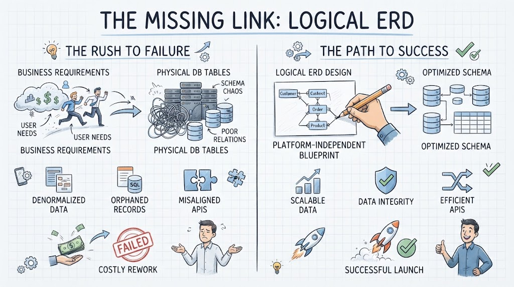
This guide demystifies the logical ERD from the ground up. We’ll explore why it exists, who relies on it, and when to create it—backed by concrete PlantUML code examples ranging from basic e-commerce to complex inheritance hierarchies. You’ll learn practical guidelines, layout tricks, and reusable macros to make your diagrams clear, consistent, and version-controllable. Finally, we’ll examine how modern tooling like Visual Paradigm, VP AI Chatbot, and VPasCode elevates logical modeling from static documentation to an active, AI-assisted engineering workflow. Whether you’re a business analyst validating requirements, a data architect enforcing standards, or a developer building ORMs, this article gives you everything needed to model data with confidence and precision.
1. Why Do We Need a Logical ERD?
A Logical ERD sits between the high-level Conceptual Model and the low-level Physical Database Schema. It is the bridge between business requirements and technical implementation.
| Feature | Conceptual ERD | Logical ERD | Physical ERD |
|---|---|---|---|
| Focus | Business Scope & Entities | Data Structure, Attributes & Relationships | Tables, Columns, Indexes, Types |
| Audience | Stakeholders, Product Owners | Business Analysts, Data Architects, Devs | DBAs, Backend Developers |
| Detail Level | Entity names only | All attributes, PK/FK, Cardinality, Normalization | Exact data types, constraints, partitions |
| DBMS Specific? | No | No (Platform Independent) | Yes (MySQL, Postgres, Oracle) |
| Primary Key | Implied | Defined | Defined + Indexed |
| Foreign Key | Not shown | Shown as relationships/attributes | Explicit columns with constraints |
The Purpose
-
Platform Independence: Design the data structure without worrying if you’ll use PostgreSQL, MongoDB, or Snowflake later.
-
Normalization Validation: Verify 3NF/BCNF compliance before writing DDL.
-
Attribute Discovery: Capture every piece of data the business needs (e.g., “Does an Order have a shipping date distinct from order date?”).
-
Communication: Serves as the single source of truth between non-technical domain experts and database engineers.
When to Use It
-
During the Requirements Analysis phase.
-
When migrating legacy systems (to map old data to new structures).
-
When designing APIs (the logical ERD often maps 1:1 to DTOs/Resources).
-
Before creating the Physical DDL.
Who Uses It
-
Data Architects: To enforce standards and normalization.
-
Business Analysts: To validate that all business rules are captured.
-
Backend Developers: To understand object-relational mapping (ORM) entities.
-
QA/Testers: To design test data scenarios based on relationships.
2. Key Concepts in Logical ERD
When drawing a Logical ERD (especially in PlantUML), focus on these elements:
-
Entities: Nouns representing business objects (e.g.,
Customer,Invoice). -
Attributes: Properties of entities. In Logical ERDs, list all relevant attributes, not just keys.
-
Primary Key (PK): Unique identifier. Must be defined for every entity.
-
Foreign Key (FK): Attribute that references another entity’s PK. Represents the relationship.
-
Cardinality:
-
One-to-One (
||--||) -
One-to-Many (
||--|{) -
Many-to-Many (
}|--|{) → Must be resolved into an associative entity in Logical ERD.
-
-
Associative Entity (Junction Table): Used to resolve M:N relationships. Contains FKs from both sides + optional descriptive attributes (e.g.,
EnrollmentbetweenStudentandCoursewithgrade). -
Inheritance (Supertype/Subtype): Represented as generalization. Important for logical modeling to avoid redundant attributes.
3. PlantUML ERD Examples
PlantUML uses a specific syntax for ERDs. Below are progressive examples.
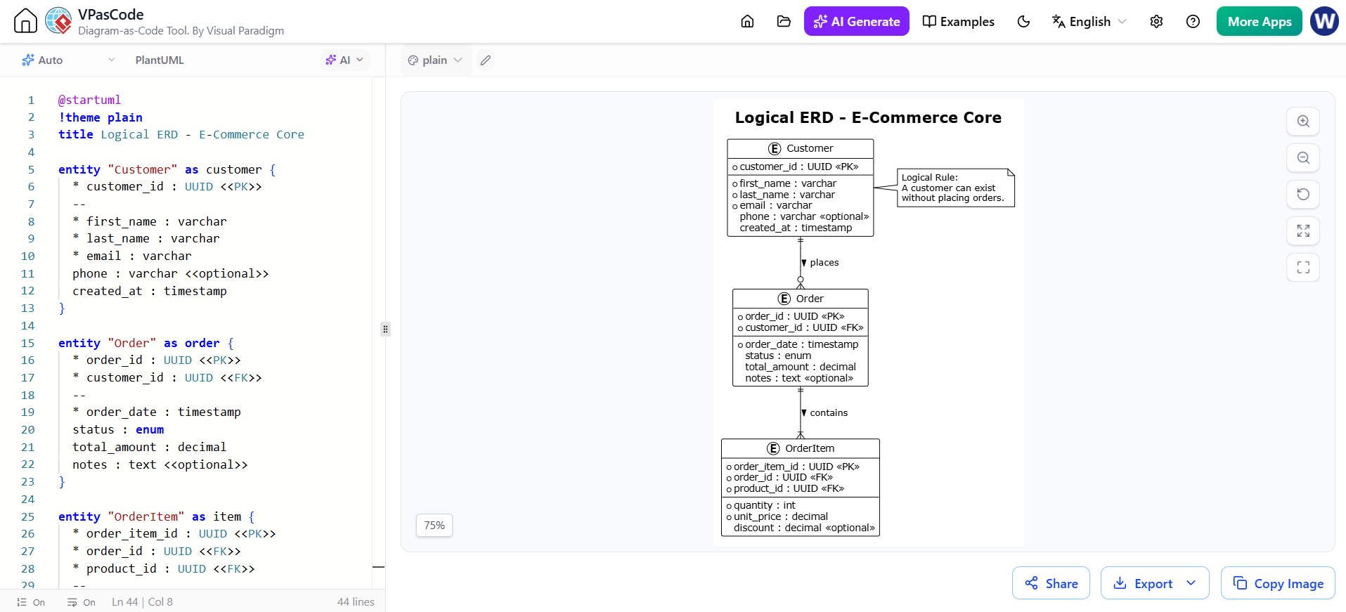
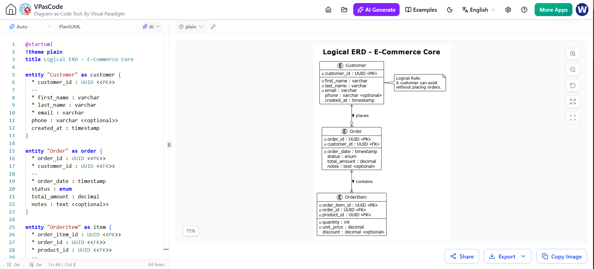
Example A: Basic E-Commerce (1:N and Attributes)
Demonstrates: Entities, PK/FK notation, One-to-Many, Mandatory vs Optional.
@startuml
!theme plain
title Logical ERD - E-Commerce Core

entity "Customer" as customer {
  * customer_id : UUID <<PK>>
  --
  * first_name : varchar
  * last_name : varchar
  * email : varchar
  phone : varchar <<optional>>
  created_at : timestamp
}

entity "Order" as order {
  * order_id : UUID <<PK>>
  * customer_id : UUID <<FK>>
  --
  * order_date : timestamp
  status : enum
  total_amount : decimal
  notes : text <<optional>>
}

entity "OrderItem" as item {
  * order_item_id : UUID <<PK>>
  * order_id : UUID <<FK>>
  * product_id : UUID <<FK>>
  --
  * quantity : int
  * unit_price : decimal
  discount : decimal <<optional>>
}

' Relationships
customer ||--o{ order : places >
order ||--|{ item : contains >

note right of customer
  Logical Rule:
  A customer can exist
  without placing orders.
end note
@enduml
Example B: Resolving Many-to-Many (Associative Entity)
Demonstrates: Converting M:N to two 1:N relationships via a junction table with payload.
@startuml
!theme plain
title Logical ERD - University Enrollment

entity "Student" as student {
  * student_id : int <<PK>>
  --
  * name : varchar
  * dob : date
  gpa : decimal
}

entity "Course" as course {
  * course_id : varchar <<PK>>
  --
  * title : varchar
  credits : int
  department : varchar
}

' ASSOCIATIVE ENTITY
entity "Enrollment" as enrollment {
  * student_id : int <<PK, FK>>
  * course_id : varchar <<PK, FK>>
  --
  * semester : varchar
  * year : int
  grade : char <<optional>>
  enrolled_date : date
}

student ||--|{ enrollment : registers >
course ||--|{ enrollment : offered_in >

note bottom of enrollment
  Composite Primary Key:
  (student_id, course_id)

  Contains descriptive attributes
  specific to the relationship.
end note
@enduml
Example C: Supertype / Subtype (Inheritance)
Demonstrates: Generalization/Specialization. Common in logical models for polymorphic entities.
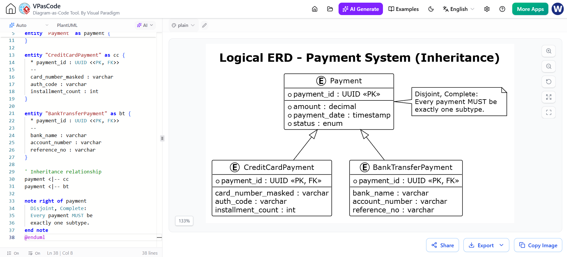
@startuml
!theme plain
title Logical ERD - Payment System (Inheritance)

entity "Payment" as payment {
  * payment_id : UUID <<PK>>
  --
  * amount : decimal
  * payment_date : timestamp
  * status : enum
}

entity "CreditCardPayment" as cc {
  * payment_id : UUID <<PK, FK>>
  --
  card_number_masked : varchar
  auth_code : varchar
  installment_count : int
}

entity "BankTransferPayment" as bt {
  * payment_id : UUID <<PK, FK>>
  --
  bank_name : varchar
  account_number : varchar
  reference_no : varchar
}

' Inheritance relationship
payment <|-- cc
payment <|-- bt

note right of payment
  Disjoint, Complete:
  Every payment MUST be
  exactly one subtype.
end note
@enduml
Example D: Complex Multi-Relationship Scenario
Demonstrates: Multiple relationships between same entities, self-referencing, and clear labeling.

@startuml
!theme plain
title Logical ERD - Project Management

entity "Employee" as emp {
  * emp_id : int <<PK>>
  --
  * name : varchar
  manager_id : int <<FK>> <<optional>>
}

entity "Project" as proj {
  * project_id : int <<PK>>
  --
  * name : varchar
  start_date : date
  end_date : date
}

entity "Assignment" as assign {
  * emp_id : int <<PK, FK>>
  * project_id : int <<PK, FK>>
  --
  * role : varchar
  allocation_pct : decimal
  start_date : date
}

' Self-referencing relationship
emp ||--o{ emp : manages >

' Standard relationships
emp ||--|{ assign : assigned_to >
proj ||--|{ assign : has >

note left of assign
  An employee can work on
  multiple projects with
  different roles.
end note
@enduml
4. Guidelines for Logical ERDs
-
Always Resolve M:N: Never leave a many-to-many line in a logical ERD. Always create an associative entity. This forces you to think about what data belongs to the relationship itself.
-
Name Attributes Clearly: Avoid abbreviations. Use
shipping_addressnotship_addr. Be consistent with snake_case or camelCase. -
Define All Keys: Every entity must have a clearly marked PK. Every relationship must show the FK attribute in the child entity.
-
Use Meaningful Relationship Labels: Label both ends of a relationship (e.g.,
places/placed_by). This eliminates ambiguity. -
Mark Optionality Explicitly: Use
<<optional>>or nullable indicators. Business rules often hinge on whether data is required. -
No Implementation Details: Do NOT specify
VARCHAR(255),INDEX,CLUSTERED, or storage engines. Use generic types likevarchar,int,decimal,timestamp. -
Normalize First: Ensure your logical model is at least in 3NF before adding denormalized fields for performance (that’s a physical concern).
5. Tips & Tricks for PlantUML ERDs
🎨 Styling & Readability
' Use themes for professional look
!theme plain
' Or customize colors
skinparam linetype ortho
skinparam entity {
  BackgroundColor #f9f9f9
  BorderColor #333333
  FontSize 12
}
📐 Layout Control
PlantUML’s auto-layout can get messy with complex ERDs. Force direction:
' Force top-to-bottom or left-to-right
left to right direction

' Use hidden links to control positioning
customer -[hidden]d- order
order -[hidden]d- item
🏷️ Stereotypes & Annotations
Use stereotypes to add semantic meaning beyond standard UML:
entity "AuditLog" as audit <<immutable>> {
  ...
}

entity "UserSession" as session <<transient>> {
  ...
}
📦 Grouping with Packages
For large diagrams, group related entities:
package "Sales Domain" {
  entity "Order" as order { ... }
  entity "Invoice" as invoice { ... }
}

package "Inventory Domain" {
  entity "Product" as product { ... }
  entity "Warehouse" as warehouse { ... }
}

order }|--|{ product : references >
⚡ Reusable Macros
Avoid repeating common audit columns:
!define AUDIT_FIELDS \
  created_at : timestamp \
  updated_at : timestamp \
  created_by : varchar \
  updated_by : varchar

entity "Customer" as customer {
  * id : UUID <<PK>>
  --
  * name : varchar
  AUDIT_FIELDS
}
🔗 Linking to Documentation
Add clickable notes or links for traceability:
note right of order
  See BR-2024-045
  [[https://wiki.internal/requirements/order-status]]
end note
✅ Checklist Before Finalizing
-
Every entity has a PK?
-
All M:N resolved to associative entities?
-
FKs explicitly listed as attributes in child entities?
-
Cardinalities correct on BOTH sides?
-
No DBMS-specific types or constraints?
-
Relationship labels read naturally in both directions?
-
Optional fields clearly marked?
-
Diagram fits on screen/print without excessive scrolling?
6. Recommended Tooling: Visual Paradigm + VP AI Chatbot + VPasCode Workflow
While PlantUML is excellent for version-controlled, code-first ERD authoring, enterprise-grade logical modeling often demands a dedicated platform that bridges the gap between visual design, AI-assisted analysis, and automated engineering. The combination of Visual Paradigm (VP), its integrated VP AI Chatbot, and the VPasCode workflow represents a standout stack for modern data architecture teams.
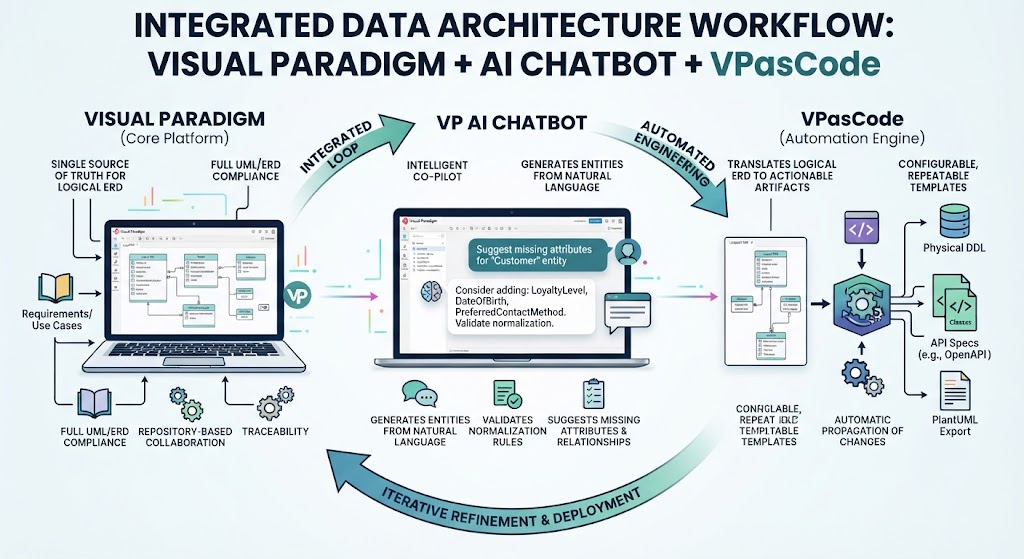
The Integrated Workflow
This trio creates a seamless loop that pure-code or pure-GUI tools cannot match independently:
-
Visual Paradigm (Core Platform): Serves as the single source of truth for your Logical ERD with full UML/ERD compliance, repository-based collaboration, and traceability to requirements.
-
VP AI Chatbot: Acts as an intelligent co-pilot inside the modeling environment. It understands your current diagram context and can generate entities from natural language, validate normalization rules, suggest missing attributes, or explain complex relationships without leaving the canvas.
-
VPasCode (Automation Engine): Translates the validated Logical ERD into actionable artifacts—Physical DDL, ORM entity classes, API specs, or even PlantUML exports—through configurable, repeatable templates. Changes in the model automatically propagate through VPasCode pipelines.
Unique & Standout Benefits
| Benefit | Why It’s Unique vs. Alternatives | Practical Impact |
|---|---|---|
| Context-Aware AI Modeling | Unlike generic AI (ChatGPT/Copilot), VP AI Chatbot operates within your project repository. It sees your existing entities, naming conventions, and business glossary, so suggestions are consistent—not hallucinated guesses. | Reduces modeling time by 40–60% while maintaining organizational standards. AI-generated entities integrate directly into the diagram, not as disconnected text. |
| Bidirectional Model-Code Sync | VPasCode isn’t just forward-engineering. It supports round-trip engineering: update your Logical ERD → regenerate DDL/entities; import DB changes → sync back to logical model. Pure PlantUML or basic GUI tools lack this bidirectional fidelity. | Eliminates model-code drift. Your Logical ERD stays alive throughout the SDLC instead of becoming stale documentation. |
| Logical-to-Physical Traceability | Visual Paradigm maintains explicit lineage between Logical ERD elements and their Physical counterparts. You can click any physical column and trace it back to the original business attribute and requirement. | Critical for audits, impact analysis, and regulatory compliance (GDPR, HIPAA). Impossible with standalone PlantUML or disconnected AI tools. |
| AI-Powered Quality Gates | VP AI Chatbot can be configured to run automated reviews against your organization’s data modeling standards before VPasCode generates artifacts. Catches anti-patterns (unresolved M:N, missing PKs, naming violations) proactively. | Shifts data quality left. Prevents costly rework in physical implementation phase. |
| Collaborative Model Repository | Unlike file-based PlantUML, VP uses a centralized team server with check-in/check-out, version history, branching, and merge capabilities specifically designed for models (not just text diffs). | Enables true parallel modeling by multiple architects without overwrite conflicts. Enterprise-scale governance. |
| Template-Driven Consistency | VPasCode uses customizable generation templates (Velocity/Groovy). Define your org’s DDL style, ORM annotations, or PlantUML format once; every generation adheres perfectly. | Ensures 100% consistency across 50+ microservices/databases. New team members produce output identical to senior architects. |
When This Stack Outshines Pure PlantUML
-
Enterprise Scale: Managing 20+ interconnected domains with shared entities and cross-team dependencies.
-
Regulated Industries: Where audit trails, traceability, and standardized review processes are mandatory.
-
Legacy Modernization: Importing existing DB schemas, using AI to reverse-engineer logical models, then forward-engineering new targets via VPasCode.
-
Team Adoption Barriers: When stakeholders resist code-only diagrams but still need engineering-grade outputs. VP provides the visual interface they want with the automation engineers demand.
Integration Note for PlantUML Users
You don’t have to abandon PlantUML entirely. Use VPasCode to export your Visual Paradigm Logical ERD as PlantUML for inclusion in Git repos, wikis, or CI/CD documentation pipelines. This gives you the best of both worlds: enterprise-grade modeling with lightweight, version-controllable visualization.
💡 Key Takeaway: PlantUML excels at documenting and communicating logical ERDs. Visual Paradigm + VP AI + VPasCode excels at creating, validating, governing, and engineering them at scale. For teams treating data modeling as a disciplined engineering practice—not just a diagramming exercise—this integrated workflow delivers ROI that standalone tools cannot match.
Conclusion
A well-crafted Logical ERD is far more than a diagram—it’s a contract between business intent and technical implementation. By investing time in this intermediate layer, teams avoid the two most expensive mistakes in data architecture: building databases that don’t reflect real business rules, and retrofitting structure after code is already written. The principles outlined here—resolving M:N relationships, defining all keys and attributes explicitly, maintaining platform independence, and labeling relationships meaningfully—form a disciplined foundation that pays dividends across development, testing, and long-term maintenance.
PlantUML provides an accessible, code-first entry point that integrates seamlessly with modern DevOps practices, making logical modeling collaborative and version-controlled. But for organizations operating at scale or under regulatory scrutiny, pairing it with an integrated platform like Visual Paradigm unlocks transformative capabilities: AI-assisted modeling that respects organizational context, bidirectional synchronization that keeps models alive, and automated generation pipelines that enforce consistency across dozens of systems. The key is recognizing that tooling should serve the discipline—not replace it.
Ultimately, the goal isn’t perfect diagrams; it’s shared understanding. When business stakeholders, data architects, and developers all see the same logical structure—and trust that it accurately reflects their domain—the resulting systems are more resilient, adaptable, and aligned with actual needs. Start with the logical model. Validate it rigorously. Automate its translation. And watch your data architecture evolve from a source of friction into a strategic asset.