Software systems and complex hardware architectures are rarely simple. As requirements grow, the internal wiring of components becomes a tangled web of interactions. Standard diagrams often show what exists, but they struggle to show how parts fit together inside a specific classifier. This is where the UML Composite Structure Diagram becomes essential. It provides a granular view of the internal structure of classifiers, revealing the relationships between parts, roles, and connectors.
Without this level of detail, architects risk building systems that are difficult to maintain or extend. Understanding the internal composition of a class or component is crucial for high-fidelity modeling. This guide explores the necessity of this diagram type and provides a clear methodology for creating one.
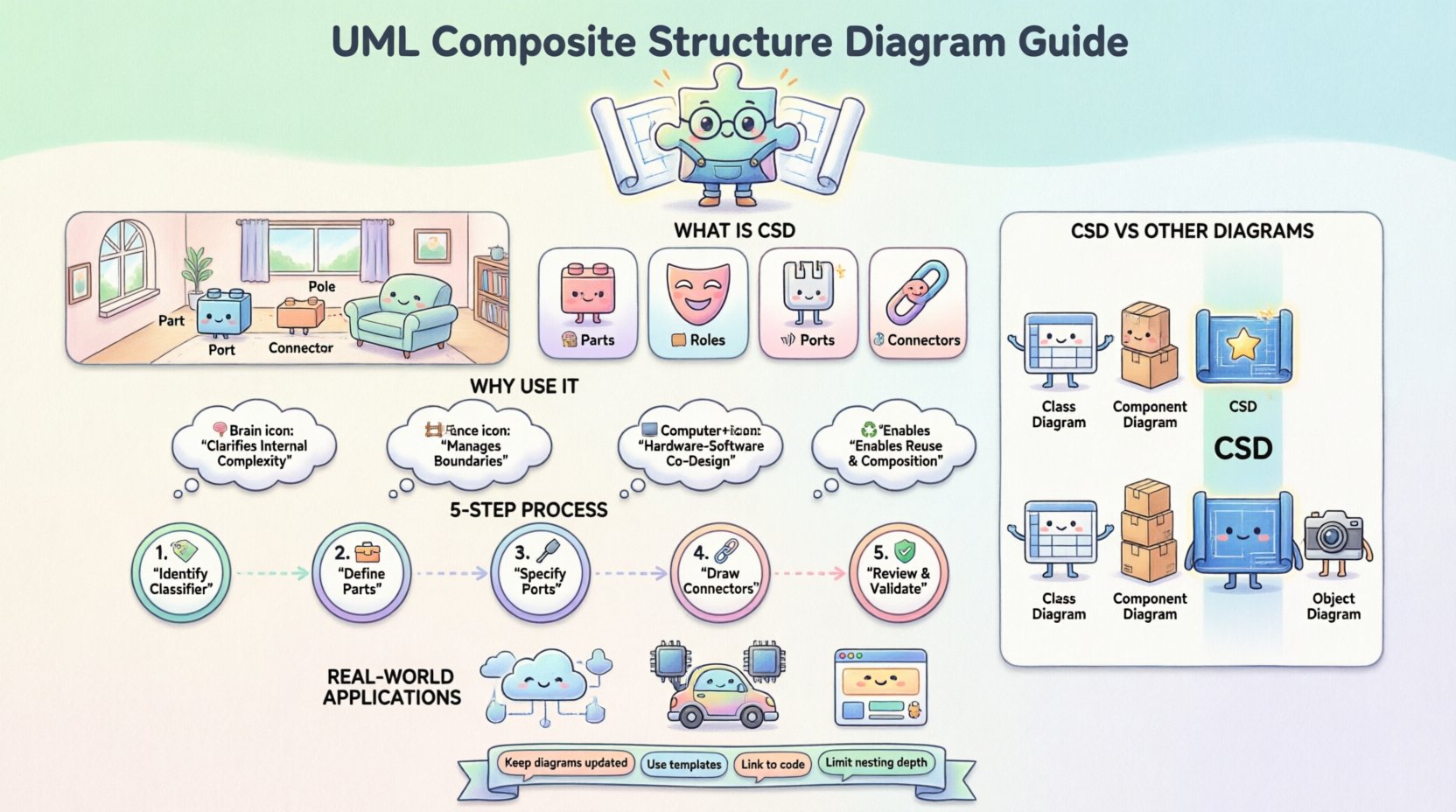
What is a Composite Structure Diagram? 🧩
A Composite Structure Diagram (CSD) is a structural diagram in the Unified Modeling Language. It models the internal structure of a classifier and the interaction between its internal parts. While a Class Diagram shows attributes and methods, and a Component Diagram shows deployable units, the CSD zooms in on the internal mechanics.
Think of it as a blueprint for a specific room in a house, rather than the floor plan of the whole building. It details:
- Parts: The individual components inside the classifier.
- Roles: The interface or responsibility a part plays.
- Ports: The points of interaction with the outside world.
- Connectors: The links between parts.
This diagram is particularly valuable when dealing with systems that require strict internal boundaries or where the internal wiring dictates system behavior.
The Anatomy of a Composite Structure Diagram 🔍
To draw an effective diagram, you must understand the building blocks. These elements define the relationships and boundaries within the system.
1. Parts 🧱
A part is an instance of a classifier that is owned by a composite classifier. It represents a component inside the larger structure. In a software context, a part might be a sub-routine, a database connection pool, or a specific module.
- Visibility: Parts can be public, private, or protected.
- Multiplicity: You can specify how many instances of a part exist (e.g., 1, 0..*, 1..1).
2. Roles 🎭
When a part interacts with another part or the outside world, it does so in a specific capacity. This capacity is the role. A single part might play multiple roles at different times or for different interactions.
- Roles are often represented by interfaces.
- They define what services the part provides or requires.
3. Ports 📡
A port is a named interaction point on a classifier. It serves as a boundary between the internal structure and the external environment. Think of a port as a socket on a motherboard; it allows external cables to connect to the internal circuitry.
- Provided Interfaces: What the port offers to others.
- Required Interfaces: What the port needs from others to function.
4. Connectors 🔗
Connectors link interaction points. They define how data or control flows between parts or between parts and the external environment.
- Internal Connectors: Link parts within the same composite classifier.
- External Connectors: Link ports of the composite classifier to other classifiers.
Why Your Architecture Needs This View 📈
Many architects rely solely on Class Diagrams or Sequence Diagrams. While useful, they often miss the structural nuance required for complex systems. Here is why you should invest time in CSDs.
1. Clarifying Internal Complexity 🧠
When a class becomes too complex, it acts as a “god object.” A Composite Structure Diagram forces you to break it down. It visualizes the delegation of responsibility. If a class has too many parts, you know it needs refactoring.
2. Managing Boundaries 🚧
Ports and interfaces define strict boundaries. They prevent internal implementation details from leaking into the public API. This supports encapsulation principles and makes the system more robust against changes.
3. Hardware-Software Co-Design 🖥️
Embedded systems often mix software and hardware. A CSD can model a microcontroller (hardware) containing a specific software driver (part). This hybrid modeling is difficult with standard UML diagrams but is native to Composite Structure Diagrams.
4. Reuse and Composition ♻️
Design patterns often rely on composition. By explicitly modeling parts, you can reuse internal structures across different classifiers. If you define a “Logging System” part once, you can plug it into multiple classifiers.
CSD vs. Other UML Diagrams 🔄
Understanding when to use a CSD requires knowing how it differs from its siblings. The following table outlines the distinctions.
| Diagram Type | Focus | Best Used For |
|---|---|---|
| Class Diagram | Static structure, attributes, methods | Database schema, general object relationships |
| Component Diagram | High-level deployment, physical files | System deployment, module boundaries |
| Composite Structure Diagram | Internal structure, parts, roles, ports | Complex internal wiring, embedded systems, detailed design |
| Object Diagram | Runtime instances at a specific moment | Snapshot of state, testing scenarios |
Notice that the CSD sits between the abstract Class Diagram and the physical Component Diagram. It bridges the gap between logical design and physical implementation.
Step-by-Step Guide to Drawing One 📝
Creating a diagram requires a methodical approach. Do not start by drawing boxes. Start by analyzing the requirements.
Step 1: Identify the Classifier 🏷️
Decide which class or component you are modeling. Is it a specific service? A hardware controller? Ensure this classifier is complex enough to warrant internal decomposition. If it only has two attributes, a CSD is overkill.
Step 2: Define the Parts 🛠️
List the internal components that make up the classifier. These should be logical units of work.
- Break down responsibilities. Does one part handle data? Does another handle logic?
- Assign multiplicities. Can there be zero parts, or must there be exactly one?
- Use standard classifiers for parts (e.g., a Database connection, a Logger).
Step 3: Specify Ports and Interfaces 🔌
For each part, determine how it communicates.
- What does this part need to function? (Required Interface)
- What does this part offer to others? (Provided Interface)
- Define the ports on the main classifier. These are the entry points for the external world.
Step 4: Draw the Connectors ⛓️
Link the parts together. This is where the logic flows.
- Connect the output of one part to the input of another.
- Ensure data types match at the connection points.
- Mark the direction of the connector if it is unidirectional.
Step 5: Review and Validate ✅
Walk through the diagram. Can the system function if a specific part fails? Are there circular dependencies? Does the external interface match the internal reality?
Real-World Applications 💻
To make this concrete, let us look at how this applies to actual engineering scenarios.
Scenario 1: Microservices Architecture 🔗
In a microservices environment, a “Payment Service” might have internal parts: a Transaction Logger, a Fraud Detector, and a Gateway Adapter. A CSD shows how the Gateway Adapter passes data to the Fraud Detector before the Transaction Logger records it. This clarifies the sequence without needing a full Sequence Diagram.
Scenario 2: Embedded Control Systems 🚗
An automotive braking system involves sensors, a controller, and actuators. A CSD models the controller’s internal logic. It shows the sensor part requiring a data stream, the calculation part using that stream, and the actuator part receiving the command. It visualizes the tight coupling between software and hardware drivers.
Scenario 3: GUI Frameworks 🖱️
A window widget often contains smaller parts: a title bar, a content area, and a close button. Each part has its own behavior. A CSD defines how these parts are arranged and how they communicate when a user clicks the close button.
Common Mistakes to Avoid ⚠️
Even experienced architects make errors when modeling. Watch out for these pitfalls.
- Over-Modeling: Do not create a CSD for every class. Only model complex structures. Use it when the internal wiring matters.
- Ignoring Multiplicity: Failing to specify how many parts exist leads to ambiguity. A system might need three instances of a buffer, not just one.
- Mixing Levels: Do not mix high-level components with low-level variables in the same diagram. Keep the granularity consistent.
- Forgotten Ports: Ensure every external interaction goes through a port. Direct links to the outside world from internal parts break encapsulation.
Best Practices for Maintenance 🛠️
Diagrams are living documents. They must evolve with the code.
- Keep it Updated: If the code changes, the diagram must change. A stale diagram creates more confusion than no diagram.
- Use Templates: If your architecture uses standard patterns, create templates for common parts. This speeds up modeling and ensures consistency.
- Link to Code: Where possible, link diagram elements to actual code repositories. This ensures traceability.
- Limit Depth: Avoid nesting diagrams too deeply. If a part needs its own CSD, link to a separate diagram rather than drawing it inline. This keeps the main view readable.
Key Elements Breakdown Table 📊
For quick reference, here is a summary of the core elements you will encounter.
| Element | Symbol | Purpose |
|---|---|---|
| Part | Rectangle with class name | Represents an instance of a classifier inside the composite. |
| Role | Interface symbol or lollipop | Defines the behavior a part exposes or requires. |
| Port | Small square on the edge | Interaction point on the classifier boundary. |
| Connector | Line with arrows | Links interaction points to allow data flow. |
| Collaboration | Dashed box with label | Groups parts and connectors to define a specific interaction context. |
Final Thoughts on Structural Integrity 🏛️
Building robust software requires more than just writing code. It requires a clear vision of how pieces fit together. The UML Composite Structure Diagram offers a rigorous way to document that vision. It forces architects to confront internal complexity head-on.
By focusing on parts, roles, and ports, you create a model that is both detailed and maintainable. It reduces the risk of hidden dependencies and clarifies how data moves through your system. While it takes extra effort to draw, the clarity it brings to the development team is worth the investment.
Start applying this technique to your most complex classes today. You will find that the internal wiring of your architecture becomes as clear as the external interface.

