Understanding the internal architecture of a system is critical for software design. While standard class diagrams show relationships between objects, they often fail to reveal how those objects are physically organized or how they interact at a granular level. This is where the UML Composite Structure Diagram comes into play. It provides a view of the internal structure of a classifier, detailing the parts that make up the whole and how they connect. 🧩
For architects and developers, mastering this specific diagram type ensures clarity in complex systems. It bridges the gap between high-level component models and detailed class implementations. This guide explores the mechanics, notation, and practical application of composite structure diagrams.
What Is a Composite Structure Diagram? 🏗️
A Composite Structure Diagram is a structural diagram in the Unified Modeling Language (UML). It illustrates the internal structure of a classifier, such as a class or an interface. Instead of treating an object as a black box, this diagram opens the box to show the constituent parts.
Key characteristics include:
- Internal Focus: It reveals the composition of a classifier.
- Interaction: It shows how internal parts communicate with each other.
- Interfaces: It specifies the roles that parts play and the ports where interaction occurs.
- Collaboration: It can depict a collaboration that defines a set of interactions.
This diagram is particularly useful when the internal arrangement of a class matters. For example, if a Car class is composed of an Engine, Wheel, and SteeringWheel, a composite structure diagram defines how these parts fit together and interact.
Core Elements and Notation 🧩
To read or create these diagrams effectively, one must understand the standard notation used. UML defines specific shapes and lines for this purpose.
1. Components and Parts 📦
A part represents an instance of a class that is owned by another class. In the diagram, this is shown as a rectangle with the name of the part type. The name of the part itself appears in italics, while the type appears in bold.
- Part: The specific instance within the composite.
- Type: The class that the part belongs to.
2. Ports 📡
Ports are the interaction points between a composite and its environment. They can also facilitate communication between internal parts. Think of a port as a socket where a plug can be inserted.
- Provided Interface: Represented by a “lollipop” shape. The part offers a service here.
- Required Interface: Represented by a “socket” shape. The part needs a service here.
3. Roles 🎭
A role specifies the perspective from which a part interacts with others. A single part might play multiple roles. For instance, a NetworkDevice might play the role of a Router in one context and a Switch in another.
- Roles are often labeled near the connector or port.
- They clarify the specific behavior expected from a part in a specific interaction.
4. Connectors 🔗
Connectors define the paths along which messages are sent. They link ports, roles, or parts together. There are two main types of connectors:
- Internal Connector: Links two parts inside the same composite. It represents internal communication.
- External Connector: Links a part to the outside world, typically connecting a port to an interface.
5. Partitions 📊
Large composites are often divided into partitions to manage complexity. A partition is a rectangle drawn inside the main classifier rectangle. It groups related parts together, improving readability.
Visualizing the Notation
When drawing these diagrams, specific visual cues help distinguish elements quickly.
- Composite Box: A large rectangle representing the classifier.
- Internal Box: A smaller rectangle inside the composite representing a part.
- Port Box: A small rectangle protruding from the internal box or the composite edge.
- Interface Symbol: The lollipop and socket icons attached to ports.
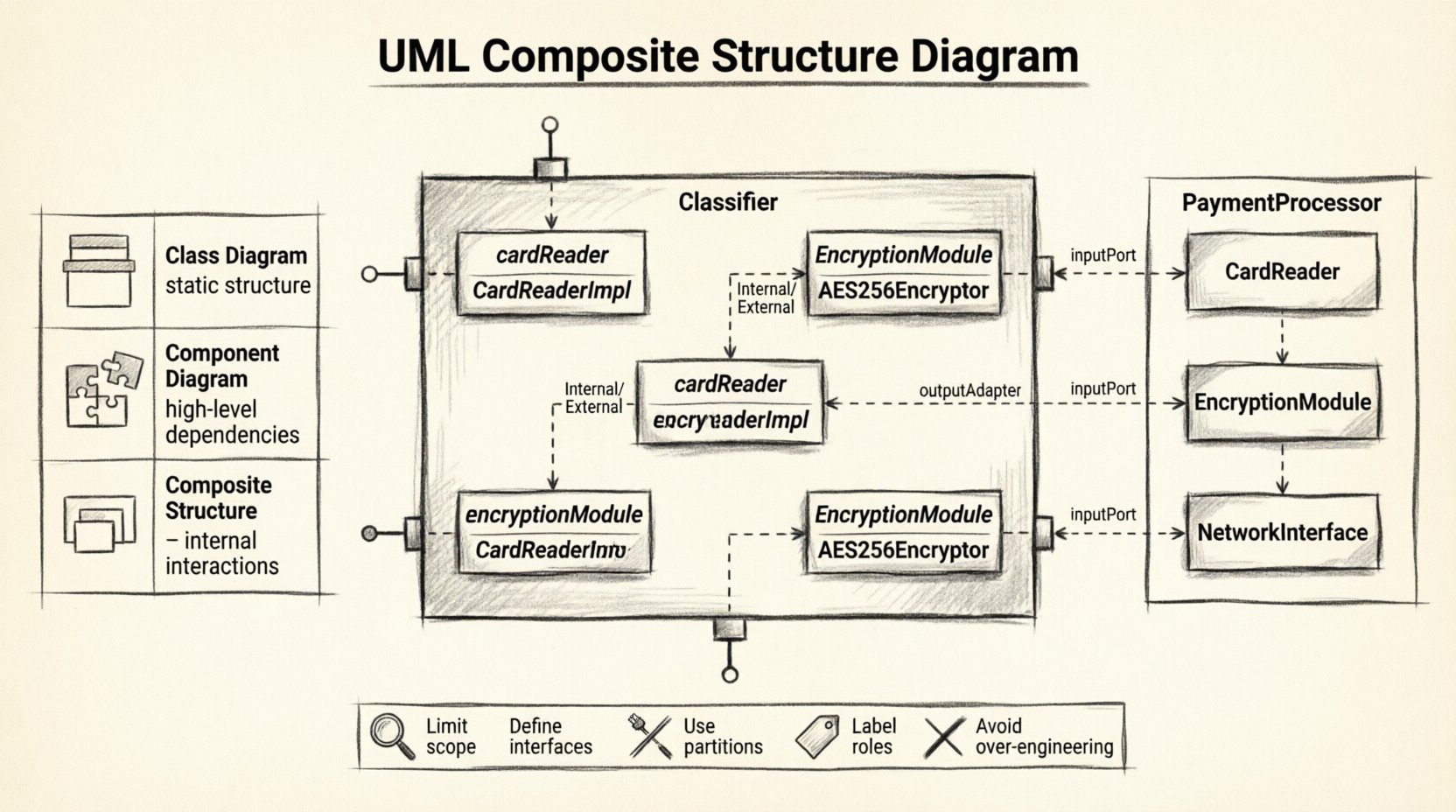
Comparison: Composite Structure vs. Other Diagrams 📋
It is common to confuse Composite Structure Diagrams with Class Diagrams or Component Diagrams. Understanding the distinction is vital for accurate modeling.
| Diagram Type | Primary Focus | Best Used For |
|---|---|---|
| Class Diagram | Static structure of classes and their attributes/methods. | Defining data structures and relationships between entities. |
| Component Diagram | High-level physical components and their dependencies. | System architecture and deployment views. |
| Composite Structure Diagram | Internal structure of a classifier and part interactions. | Complex object composition and internal collaboration logic. |
While a Class Diagram shows that a House has Rooms, a Composite Structure Diagram shows the internal wiring of the House system, including how the Door part connects to the SecuritySystem part via a specific port.
When to Use This Diagram 💡
Not every system requires a composite structure diagram. Use it when the internal arrangement adds value to the understanding of the design.
- Complex Aggregations: When a class is made up of many other classes that need to collaborate.
- Hardware/Software Integration: When modeling embedded systems where physical parts interact logically.
- Interface Contracts: When defining strict interaction points between parts of a system.
- Refactoring: When analyzing existing code to understand how parts are coupled before making changes.
Frequently Asked Questions (Q&A) ❓
Q: Can I use this diagram for simple classes?
A: Generally, no. If a class has no internal structure or complex interactions, a standard class diagram suffices. Composite structure diagrams add overhead. Use them only when the internal parts and their connections are significant to the system’s design.
Q: How does this differ from a Component Diagram?
A: A Component Diagram focuses on replaceable parts of a system that can be deployed independently. A Composite Structure Diagram focuses on the internal composition of a single classifier. Think of the Component Diagram as the building blueprint, and the Composite Structure Diagram as the interior room layout.
Q: Do ports have to be visible?
A: Yes, ports are explicit interaction points. If a part communicates internally without an interface, it is often modeled as a direct connection between attributes or operations, but ports are the standard for interaction boundaries.
Q: Can I mix UML versions?
A: This diagram exists in UML 2.0 and later. It is a stable feature of the standard. Ensure your tools support UML 2.x to render the specific symbols for ports and roles correctly.
Q: Is it possible to have recursive composition?
A: Yes. A part can be of the same type as the composite. For example, a Folder class containing other Folder classes. The diagram handles this by nesting the composite structure within itself.
Construction Best Practices 🛠️
Creating a useful diagram requires discipline. Follow these guidelines to maintain clarity.
1. Limit the Scope
Do not attempt to model the entire system in one diagram. Focus on a specific classifier that has complex internal structure. If the diagram becomes too crowded, split it into multiple views.
2. Define Interfaces Clearly
Ensure that every port has a well-defined interface. If a port does not specify what it provides or requires, the interaction is ambiguous. Use explicit interface names.
3. Use Partitions for Grouping
As the number of parts increases, use partitions to group them logically. This reduces visual noise and helps the reader understand the subsystem organization.
4. Label Roles Consistently
Roles should be named based on the behavior they provide, not just the class name. For example, use InputHandler instead of just InputDevice.
5. Avoid Over-Engineering
Do not model internal variables or private methods unless they are relevant to the interaction. Focus on the structural relationships and ports.
Common Mistakes to Avoid ⚠️
Even experienced modelers make errors. Being aware of common pitfalls can save time.
- Confusing Parts with Associations: An association is a relationship between two classifiers. A part is an owned element inside a classifier. Do not draw an association line where a part should be.
- Ignoring Multiplicity: Remember that a part can have a multiplicity (e.g., one to many). Ensure the notation reflects whether you have one instance or multiple instances of a part.
- Overloading Ports: A port can have multiple interfaces, but too many can confuse the viewer. Keep the contract clear.
- Neglecting Internal Connectors: If parts interact, show the path. Do not assume the reader knows how data flows between internal parts without a connector.
Benefits of Using Composite Structure Diagrams ✅
Why invest time in this diagram type? The advantages are tangible for system integrity.
- Clarity: It removes ambiguity about how parts fit together.
- Decoupling: It encourages defining interfaces (ports) rather than direct dependencies, leading to looser coupling.
- Documentation: It serves as a high-fidelity reference for developers implementing the class internals.
- Validation: It helps validate that the internal structure supports the external behavior defined in sequence or use case diagrams.
Integration with Other Models 🔗
This diagram does not exist in isolation. It works alongside other UML artifacts.
- Class Diagram: The composite structure diagram refines the class definitions found in the class diagram.
- Sequence Diagram: The sequence diagram can show the dynamic message flow that occurs through the ports defined in the composite structure diagram.
- State Machine Diagram: If the composite contains state logic, the state machine diagram can describe the behavior of the whole or its parts.
Practical Example: A Payment System 🏦
Consider a PaymentProcessor class. It is not just a single block of code; it is composed of several parts.
- Part 1:
CardReader(Role:InputDevice) - Part 2:
EncryptionModule(Role:SecurityProvider) - Part 3:
NetworkInterface(Role:Gateway)
In the diagram:
- The
PaymentProcessorcontains theCardReaderpart. - The
CardReaderhas a port requiring theInputinterface. - The
EncryptionModuleprovides theSecureProcessinginterface. - An internal connector links the
CardReaderport to theEncryptionModuleport. - The
PaymentProcessorexposes a port to the outside world forPaymentValidation.
This visualization makes it clear that data flows from the reader, through encryption, and out via the gateway, without the external user needing to know the internal steps.
Advanced Considerations 🔍
For complex systems, there are advanced features to consider within the composite structure.
1. Nested Composites
A part can itself be a composite structure. This allows for hierarchical modeling. You can drill down into a part to see its internal structure if it is complex enough to warrant it.
2. Behavior Specifications
You can specify the behavior of a part using a state machine or activity diagram within the composite structure diagram. This links the static structure directly to dynamic behavior.
3. Constraints
Constraints can be applied to parts, ports, or connectors. For example, you might specify that a connector must not have a delay greater than 50ms. These are often written in curly braces { }.
Summary of Key Takeaways 📝
- Internal View: Use this diagram to see inside a classifier.
- Parts and Ports: Parts are the components; ports are the interaction points.
- Interfaces: Define what parts provide and require clearly.
- Connectors: Show the paths for data flow between parts.
- Clarity: Use partitions to manage complexity.
By utilizing the UML Composite Structure Diagram, you gain a precise tool for defining the internal mechanics of your software. It moves beyond simple relationships to show the physical and logical assembly of your system components. This level of detail supports robust design and easier maintenance.
When planning your next complex object-oriented design, consider whether the internal composition requires explicit modeling. If it does, this diagram is the standard solution for the task. Ensure your team understands the notation to maintain consistency across the documentation.