A UML Composite Structure Diagram serves as a critical blueprint within software architecture. It details the internal organization of a classifier, revealing how its parts interact to fulfill specific behaviors. Unlike a standard Class Diagram, which focuses on static relationships, this diagram exposes the structural composition of complex systems. Ensuring accuracy at this stage prevents significant technical debt during implementation. The following guide outlines essential verification steps to maintain integrity in your modeling process.
Understanding the Internal Architecture 🏗️
Before diving into the specific checklist items, it is vital to understand what constitutes a valid Composite Structure Diagram. This visual representation illustrates the internal structure of a classifier. It shows the parts that make up the classifier, the interfaces they provide or require, and the connectors that link them. Accuracy here ensures that developers understand how components collaborate internally. Errors in this diagram can lead to miscommunication regarding data flow, dependency injection, or interface implementation.
Essential Verification Steps for Model Integrity ✅
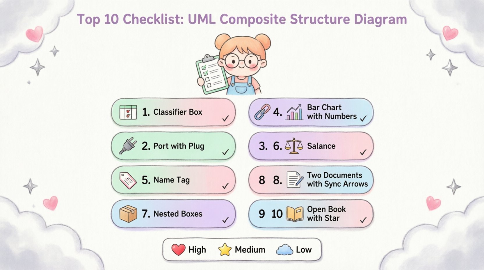
Completing a diagram is not enough. Validation is required to ensure the model reflects the intended design. Use the following ten points to audit your work before moving to the next phase of development.
1. Verify Classifier Participation 🚦
Every part within the composite structure must belong to a valid classifier. This means checking that each part is typed by a class, component, or interface that exists within the broader system context. If a part references a type that is undefined, the diagram loses its semantic meaning. Ensure that the classifier definition matches the requirements of the parent structure.
- Confirm the part type is declared elsewhere.
- Check for typos in class names.
- Ensure inheritance hierarchies are respected.
2. Validate Port and Interface Definitions 🔌
Ports act as interaction points where a part communicates with the outside world or other internal parts. Interfaces define the contract for this communication. You must verify that every port has a corresponding interface definition. A port without an interface is ambiguous and creates uncertainty about the expected behavior.
- Are all provided interfaces correctly labeled?
- Do required interfaces match the capabilities of connected parts?
- Is the direction of interaction clear (provided vs. required)?
3. Check Connector Connectivity 🔗
Connectors represent the links between ports. They facilitate the flow of data or signals. A common error is connecting a port to a part directly rather than to another port. Connectors must bridge two ports or a port and an external boundary. Verify that the connection logic aligns with the system’s interaction model.
- Ensure connectors link port to port.
- Verify multiplicity on the connector end.
- Check for overlapping or conflicting connections.
4. Ensure Multiplicity Accuracy 📊
Multiplicity defines how many instances of a part can exist within the composite structure. Incorrect multiplicity can lead to memory leaks, null pointer exceptions, or resource exhaustion in the final code. Review the cardinality notation on every association end within the diagram.
- Is a single instance (1) appropriate, or are there multiple (0..*)?
- Does the minimum multiplicity allow for null states?
- Are upper bounds set realistically for system capacity?
5. Review Role Names 🏷️
Roles provide context to associations. A part does not just connect to another; it connects to another in a specific capacity. Clear role names improve readability and reduce ambiguity for future maintainers. Avoid generic names like “Part1” or “Link2”. Instead, use descriptive terms like “DatabaseDriver” or “UserSession”.
- Are role names unique within the scope?
- Do they describe the function of the connection?
- Are they consistent with naming conventions used in the codebase?
6. Validate Constraint Adherence ⚖️
Constraints define rules that must be followed for the structure to be valid. This includes preconditions, postconditions, and invariants. If the diagram implies a rule but does not document it, developers may implement logic that violates system integrity. Use OCL (Object Constraint Language) or clear textual notes to specify these rules.
- Are lifecycle constraints documented?
- Do constraints reflect business rules?
- Is the scope of the constraint clear?
7. Check for Nested Parts 📦
Composite structures often contain nested parts. A part might itself be a composite structure. This hierarchy can become complex quickly. Ensure that nested structures are clearly delineated and that their internal ports are accessible from the outer context if required. Misplaced nesting can obscure the actual data flow.
- Is the nesting depth logical?
- Are internal ports of nested parts exposed correctly?
- Does the nesting support the decomposition strategy?
8. Confirm Consistency with Class Diagrams 📝
The Composite Structure Diagram must align with the Class Diagram. If a class is defined in the Class Diagram, its internal structure should not contradict the attributes or methods defined elsewhere. Inconsistencies here create confusion during the coding phase. Cross-reference the definitions to ensure a single source of truth.
- Do attribute types match?
- Are method signatures consistent?
- Does the visibility (public, private) match the diagram?
9. Validate Navigation Paths 🔄
Navigation paths determine how one part accesses another. In some designs, navigation is bidirectional; in others, it is restricted to a specific direction. Verify that the navigability flags on associations reflect the actual access patterns. Incorrect navigation settings can lead to tight coupling.
- Is navigation directional where necessary?
- Are dependencies minimized?
- Does the path support the intended data flow?
10. Review Documentation and Metadata 📚
Finally, ensure that the diagram includes sufficient metadata. Comments, legends, and version information help other engineers understand the intent behind the design. A diagram without context is difficult to maintain over time. Add notes explaining complex interactions or specific design decisions.
- Is the diagram versioned?
- Are complex parts explained in notes?
- Is the legend up to date?
Summary of Verification Criteria 📋
The table below summarizes the critical aspects to review during your final audit. This quick reference can help streamline the validation process.
| Checklist Item | Focus Area | Common Error | Priority |
|---|---|---|---|
| Classifier Participation | Types & Definitions | Undefined Types | High |
| Port & Interface | Interaction Points | Missing Interfaces | High |
| Connector Connectivity | Links & Paths | Part-to-Part Links | Medium |
| Multiplicity | Cardinality | Incorrect Bounds | High |
| Role Names | Association Labels | Ambiguous Naming | Medium |
| Constraints | Rules & Logic | Missing Preconditions | High |
| Nested Parts | Hierarchy | Deep Complexity | Medium |
| Class Diagram Consistency | Alignment | Attribute Mismatch | High |
| Navigation Paths | Access Control | Unnecessary Coupling | Medium |
| Documentation | Maintainability | Missing Context | Low |
Common Pitfalls in Internal Structure Modeling ⚠️
Even experienced architects encounter recurring issues when modeling composite structures. Being aware of these pitfalls can save significant time during the review phase.
Over-Engineering the Structure
It is easy to create a diagram that is overly detailed for the current scope. Every class should not necessarily be decomposed into its internal parts. Focus on components that have complex internal interactions. Simpler classes can remain as standard class definitions to avoid clutter.
Ignoring Lifecycle States
Parts often have lifecycle states that affect their availability. A database connection might be closed, or a service might be initializing. If the diagram does not account for these states, runtime errors may occur. Consider adding state information where critical.
Disregarding External Dependencies
A composite structure does not exist in isolation. It interacts with external systems. Ensure that the boundaries of the diagram clearly indicate external dependencies. This prevents assumptions about internal availability of external resources.
Integrating with Broader System Design 🔗
The Composite Structure Diagram is one piece of the larger modeling puzzle. It works in tandem with Sequence Diagrams, State Machine Diagrams, and Component Diagrams. When updating the composite structure, ensure that changes are reflected in the interaction diagrams. This alignment ensures that the static structure supports the dynamic behavior.
For instance, if a new port is added to the composite structure, the Sequence Diagram must be updated to show messages passing through that port. This holistic approach maintains consistency across all documentation artifacts.
Final Review Strategies for Model Accuracy 🔍
Before considering the diagram complete, perform a final walkthrough. Walk through the data flow from an external trigger to the internal processing and back to the output. This simulation helps identify gaps in the connectivity or missing ports. Peer review is also highly effective. Another set of eyes can spot inconsistencies that the primary author might overlook due to familiarity bias.
Maintaining high-quality models reduces the risk of architectural drift. Regular updates to the diagrams as the system evolves ensure that the documentation remains a reliable reference. This practice supports long-term maintainability and reduces the cognitive load on new team members joining the project.
By adhering to this checklist and maintaining a disciplined approach to modeling, you ensure that the internal structure of your system is robust, clear, and ready for implementation. Focus on clarity and precision in every element to support the development lifecycle effectively.

