In modern system design, the gap between written requirements and visual architecture is often where misunderstandings begin. Developers read text, stakeholders read stories, and architects read diagrams. Bridging this divide requires a precise method for converting textual logic into sequence flows. This process ensures that the dynamic behavior of a system is documented clearly, reducing ambiguity before a single line of code is written.
Why Translate Text to Sequence Flows? 🤔
Textual artifacts like user stories, API specifications, or requirement documents are linear. They describe events one after another. However, software systems operate concurrently and asynchronously. A sequence diagram captures the temporal ordering of interactions between participants. It answers the critical question: Who talks to whom, when, and in what order?
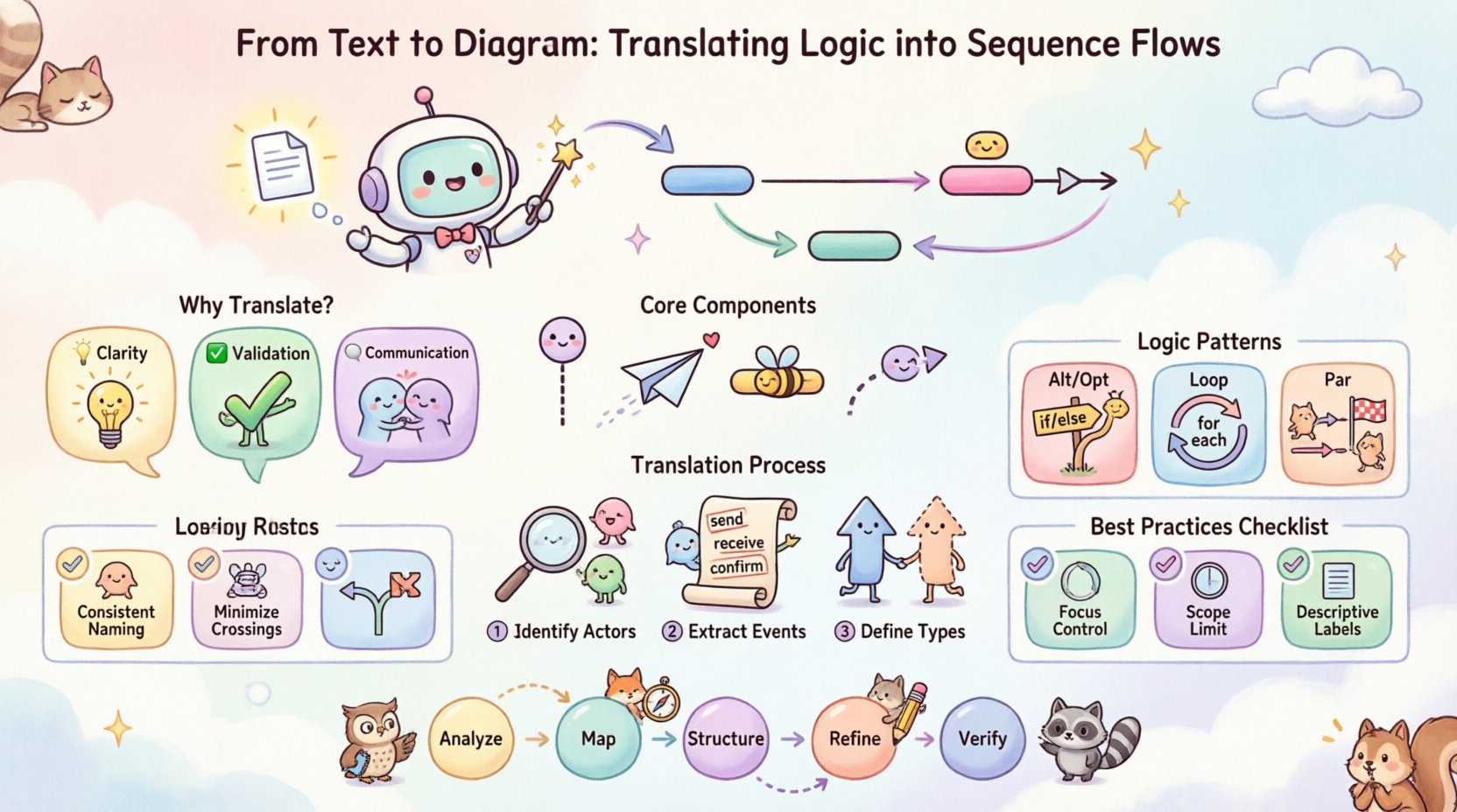
- Clarity: Visualizing the flow exposes logical gaps that text often hides.
- Validation: Teams can verify if the implementation matches the intended behavior.
- Communication: A shared visual language reduces friction between technical and non-technical roles.
When you translate logic into diagrams, you are not just drawing boxes and arrows. You are modeling the runtime behavior of your software. This guide details the systematic approach to performing this translation accurately.
Core Components of a Sequence Diagram 🧱
Before converting text, you must understand the vocabulary of the diagram. Every element serves a specific purpose in representing system state and interaction.
- Lifelines: Representing a participant in the interaction. This could be a user, an external service, a database, or a specific class instance. It is drawn as a vertical dashed line extending from the top.
- Messages: Representing communication between lifelines. Arrows indicate the direction of the call or signal.
- Activation Bars: Rectangular boxes on a lifeline indicating the period during which an object is performing an action. It shows when a process is active.
- Return Messages: Often shown as dashed lines pointing back to the sender, indicating a response or completion of a task.
Mapping Textual Cues to Diagram Elements
Not every word in a requirement document translates directly to a visual element. Some phrases imply specific diagrammatic structures.
| Textual Indicator | Diagram Element | Context |
|---|---|---|
| “When user clicks…” | Synchronous Message | User initiates action, system waits. |
| “Send notification” | Asynchronous Message | Fire-and-forget signal. |
| “If validation fails…” | Alt Frame / Option | Conditional branching. |
| “Repeat for each item” | Loop Frame | Iteration over a collection. |
| “Response received” | Return Message | Data flowing back to caller. |
The Translation Process: Step by Step 📝
Converting abstract text into a concrete diagram requires a disciplined workflow. Rushing this step often leads to incomplete models. Follow this structured approach.
1. Identify the Actors and Objects
Read the text and list every entity involved in the scenario. These become your lifelines.
- Look for nouns that represent people (e.g., “Admin”, “Customer”).
- Identify system components (e.g., “Database”, “API Gateway”, “Payment Service”).
- Determine the primary actor who initiates the sequence.
Order these lifelines horizontally. Place the initiator on the far left. This establishes the flow direction.
2. Extract the Event Chain
Scan the text for verbs that indicate action. These become your messages. Write them down in chronological order.
- Input: What starts the process?
- Processing: What calculations or checks happen?
- Output: What is the final result?
Example: If the text says, “The system validates the token, fetches the profile, and displays the data”, you have three distinct messages to place on the diagram.
3. Define the Interaction Types
Not all messages are the same. You must determine if the interaction is synchronous or asynchronous.
- Synchronous: The sender waits for a response. Use a solid line with a filled arrowhead.
- Asynchronous: The sender continues without waiting. Use a solid line with an open arrowhead.
- Return: Data sent back. Use a dashed line with an open arrowhead.
Handling Complex Logic Patterns 🧩
Real-world logic is rarely linear. Text descriptions often contain conditions, loops, and parallel processes. Sequence diagrams have specific frames to handle these complexities.
Alternative and Option (Alt / Opt)
When text includes conditional logic like “If X, do Y; otherwise do Z”, use the Alt frame. If the condition is optional, use the Opt frame.
- Label the frame with the condition (e.g., “[User Logged In]”).
- Divide the frame into operands (e.g., “[True]”, “[False]”).
- Draw the messages specific to each condition inside the operand.
Looping Structures
Text often implies repetition without stating it explicitly. Phrases like “Process all orders” or “For each item in the list” require a Loop frame.
- Draw a box around the repeated interactions.
- Label the frame “Loop”.
- Specify the condition (e.g., “[While items exist]”).
Parallel Execution
Some systems handle tasks concurrently. If the text states that multiple actions happen at the same time, use the Par frame.
- Draw a box encompassing the parallel lifelines.
- Label the frame “Parallel”.
- Ensure the messages within the frame start at the same vertical level.
Common Pitfalls in Translation ⚠️
Avoiding common errors ensures the diagram remains a useful tool rather than a source of confusion. Review your work against these common issues.
| Pitfall | Consequence | Correction |
|---|---|---|
| Missing Return Messages | Unclear if data was retrieved | Always show the response flow for synchronous calls. |
| Incorrect Lifeline Order | Confusing caller hierarchy | Keep the initiator on the far left. |
| Overcrowded Lifelines | Diagram becomes unreadable | Group interactions or split into sub-scenarios. |
| Ambiguous Messages | Developers guess the payload | Label messages with specific action names (e.g., “getProfile”, not “get”). |
| Ignoring Time | Timing constraints lost | Use notes or strict ordering for time-sensitive logic. |
Best Practices for Readability 📖
A diagram that is hard to read fails its purpose. Adhere to these guidelines to maintain clarity.
- Consistent Naming: Use the same terms for lifelines and messages throughout the document. If a lifeline is called “User”, do not switch to “Client” later.
- Minimize Crossing Lines: Arrange lifelines so arrows do not cross unnecessarily. This can be done by reordering participants.
- Focus of Control: Only draw activation bars when an object is actively processing. Do not leave them hanging indefinitely.
- Scope Limitation: One diagram should cover one specific scenario. Do not try to document the entire system lifecycle in a single image. Break complex flows into Happy Path and Error Handling diagrams.
- Descriptive Labels: Avoid generic labels. Instead of “Data”, use “User Credentials” or “Order ID”.
Validating the Logic ✅
Once the diagram is drawn, it must be validated against the original text. This step ensures fidelity.
The Walkthrough Method
Read the text aloud while tracing the diagram path.
- Does every sentence in the text have a corresponding arrow or box?
- Are there any arrows in the diagram that have no text justification?
- Do the return messages align with the expected data flow?
Edge Case Verification
Check the diagram for failure states.
- What happens if the database is down? Is there an error path?
- Does the diagram cover authentication failures?
- Are timeout scenarios represented if relevant?
Advanced Considerations 🚀
As systems grow, simple sequences become insufficient. Advanced modeling techniques help manage complexity.
Message Ordering
Sequence diagrams imply strict ordering. If multiple messages are sent without waiting, use the Par frame or group them within the same activation bar to indicate concurrency.
State Changes
While sequence diagrams focus on interactions, they can imply state changes. If an object changes state significantly, consider adding a note or linking to a state diagram for detailed state logic.
Documentation Consistency
Ensure the diagram matches other documentation. If the API spec says a method is “POST /orders”, the message label should reflect this. Consistency across documents builds trust in the design.
Iterative Refinement 🔄
Translation is rarely perfect on the first try. Treat the diagram as a living artifact.
- Feedback Loops: Share drafts with developers early. They may spot logical impossibilities in the text.
- Versioning: If requirements change, update the diagram immediately. An outdated diagram is worse than no diagram.
- Refactoring: If a diagram becomes too large, extract sub-sequences. Use references to link them together.
Summary of the Workflow
To summarize the translation process effectively:
- Analyze: Read the text and identify actors.
- Map: List messages and their types.
- Structure: Arrange lifelines and draw the flow.
- Refine: Add frames for logic (Alt, Loop, Par).
- Verify: Cross-check against requirements.
By following this structured approach, you ensure that the visual representation of your system accurately reflects the intended logic. This reduces the risk of misinterpretation and streamlines the development process. The goal is not just to draw a diagram, but to communicate the behavior of the system with precision.
Remember that the value lies in the clarity of the communication. A well-constructed sequence diagram serves as a blueprint for implementation and a reference for maintenance. Invest the time to get the translation right, and the downstream benefits in code quality and system reliability will follow naturally.

