Software systems grow in complexity. What begins as a simple monolith often evolves into a distributed network of services, databases, and interfaces. With this growth comes a significant challenge: communication. Architects, developers, and stakeholders often struggle to understand the same system because they are looking at it through different lenses. Some see high-level business flows, while others focus on specific database schemas. This disconnect creates architectural confusion, leading to implementation errors, technical debt, and slowed development cycles.
The C4 Model provides a structured approach to software architecture documentation. It is not a specific tool or a piece of software but rather a conceptual framework. It helps teams create diagrams that are clear, consistent, and useful at various levels of abstraction. By adopting this model, organizations can reduce ambiguity and ensure everyone shares a common understanding of how the system works. This guide explores how to apply the C4 Model effectively to bring clarity to complex systems.
🧩 The Core Philosophy of Abstraction
One of the primary causes of confusion in architecture is the lack of appropriate abstraction. When a diagram shows every single class and method, it becomes unreadable for anyone outside the immediate development team. Conversely, a diagram that only shows boxes and arrows without context fails to explain the actual data flow or responsibilities. The C4 Model addresses this by defining four distinct levels of detail.
Each level serves a specific audience and answers a specific set of questions. The model encourages teams to start high-level and drill down only when necessary. This ensures that the documentation remains relevant and does not become obsolete as code changes. The core philosophy rests on the idea that different stakeholders need different views.
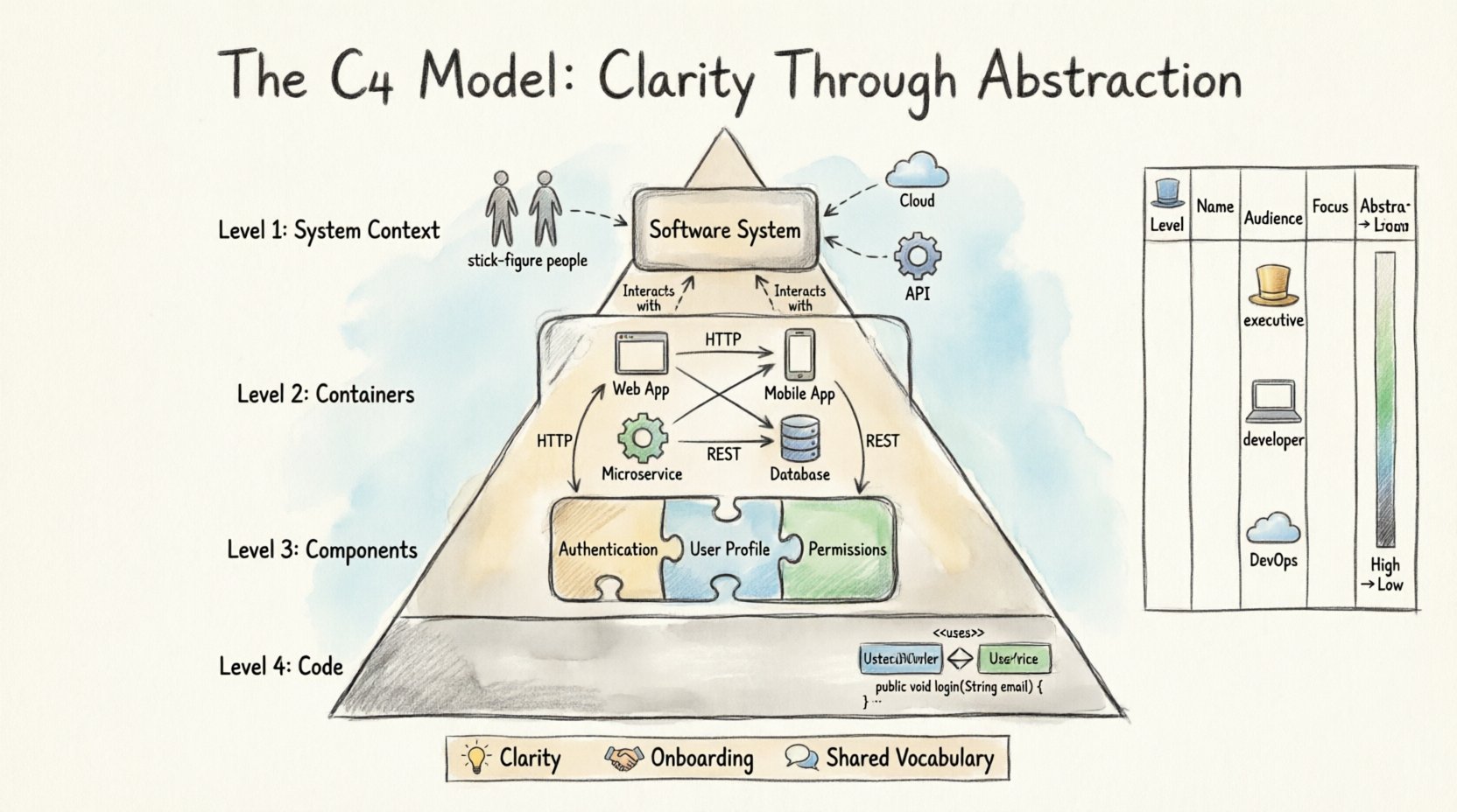
- Executives need to know the business value and high-level interactions.
- Developers need to understand how components interact to build features.
- DevOps Engineers need to know about deployment and infrastructure.
By separating these concerns, the C4 Model prevents the “one size fits all” problem that plagues many documentation efforts.
🌍 Level 1: System Context
The System Context diagram is the starting point for understanding a software system. It provides the broadest view possible. This diagram answers the question: “What is the system, and who interacts with it?” It defines the boundary between your system and the external world.
At this level, the system is represented as a single box. This box contains the name of the software product or service. Surrounding this box are the people and systems that interact with it. These external entities are known as “people” or “software systems.” The lines connecting them represent the data flow or communication paths.
Key Elements of Level 1
- System Box: Represents the boundary of your software. It does not show internal details.
- People: Users, administrators, or external roles interacting with the system.
- Software Systems: Third-party APIs, other internal services, or databases external to the boundary.
- Relationships: Arrows indicating the direction of data flow.
For example, in a retail application, the System Context would show the “Online Store” box connected to “Customers,” “Payment Gateway,” and “Inventory System.” This view is crucial for onboarding new team members. It sets the stage for everything else by defining what is inside and what is outside.
When creating a System Context diagram, avoid listing internal components. Keep the focus strictly on the boundary. If a diagram at this level becomes cluttered, it usually means the system boundary is too large or too small. Adjusting the scope is a key skill in architectural design.
📦 Level 2: Containers
Once the boundary is established, the next step is to look inside the system box. The Containers level reveals the high-level building blocks that make up the software. A container is a deployable unit of software. It is a physical or logical structure that houses code and data.
Common examples of containers include web applications, mobile apps, microservices, and databases. This level is often the most useful for developers. It helps them understand where to write code and how the pieces of the puzzle fit together.
Defining a Container
- Web Application: A server-side application running on a web server.
- Mobile Application: A native or hybrid app installed on a device.
- Microservice: A small, independent service running in a process.
- Database: A storage system for persistent data.
- File Store: A repository for static assets like images or documents.
The relationships between containers are critical. They show how data moves from one part of the system to another. For instance, a mobile app might communicate with a web application, which in turn queries a database. Understanding these flows is essential for troubleshooting performance issues and security vulnerabilities.
Visualizing Level 2
When drawing this level, focus on the technology stack without getting bogged down in implementation details. A container box should be labeled with the technology used, such as “React App” or “PostgreSQL.” This provides immediate context for the team without requiring them to read code comments.
It is important to distinguish between a container and a component. A container is a deployment unit, while a component is a logical unit within that container. Confusing these two leads to diagrams that are too detailed for a high-level view.
🧩 Level 3: Components
Inside a container, there are usually many moving parts. The Components level breaks down a single container into its functional parts. This level is where the logic of the application lives. It is the most common level used by developers during the design and implementation phase.
A component represents a logical unit of code. It could be a class, a module, a package, or a function. The goal is to group related functionality together. For example, in a user management container, you might have components for “Authentication,” “User Profile,” and “Permissions.”
Benefits of Component Diagrams
- Clarity: Shows how responsibilities are divided.
- Independence: Highlights dependencies between parts of the code.
- Onboarding: Helps new developers understand the code structure quickly.
At this level, relationships are even more detailed. You can see which component calls which other component. This helps in identifying circular dependencies, which are a common source of bugs and maintenance headaches. By visualizing these connections, teams can refactor code to improve modularity.
When to Use Level 3
Not every container needs a component diagram. If a container is simple, a single box might suffice. However, if a container has complex logic, breaking it down is necessary. The decision to create a Level 3 diagram should be based on the complexity of the code and the need for communication.
Do not attempt to diagram every single class. This leads to information overload. Focus on the major architectural blocks that define the behavior of the system. Think of it as a map of the neighborhood rather than a map of every street.
💻 Level 4: Code
The final level of the C4 Model is the Code level. This is where the details of the implementation are shown. It includes class diagrams, sequence diagrams, and data models. While powerful, this level is often the least necessary for general architectural communication.
Code diagrams are highly volatile. As soon as a developer changes a variable name or moves a method, the diagram becomes outdated. Because of this, the C4 Model suggests using code diagrams only when absolutely necessary.
Use Cases for Level 4
- Complex Algorithms: When the logic is too intricate for text alone.
- Database Schemas: Showing table relationships and foreign keys.
- API Specifications: Detailed request and response structures.
Modern development practices often rely on code comments and auto-generated documentation to replace manual code diagrams. If you choose to maintain Level 4 diagrams, consider using tools that can extract this information directly from the codebase. This reduces the maintenance burden significantly.
Remember that code diagrams should support the higher-level views, not replace them. A developer might need to see a sequence diagram to understand a specific bug, but they do not need to see it to understand the overall system design.
📊 Comparing the Levels
To make the distinctions clear, here is a summary table comparing the four levels of the C4 Model.
| Level | Name | Who Uses It? | Focus | Abstraction |
|---|---|---|---|---|
| 1 | System Context | Stakeholders, Architects | Boundary & External Systems | High |
| 2 | Containers | Developers, DevOps | Deployment Units | Medium |
| 3 | Components | Developers | Logical Code Structure | Low |
| 4 | Code | Developers | Implementation Details | Very Low |
This table highlights the progression from business context to technical detail. Moving from Level 1 to Level 4 increases detail but decreases the breadth of understanding. A good architecture strategy balances these levels based on the audience.
🛠️ Implementation Strategy
Adopting the C4 Model requires a shift in how teams approach documentation. It is not about drawing more pictures; it is about drawing the right pictures. Here is a practical approach to implementing this model in a project.
1. Start with the Context
Begin every new project by defining the System Context. Gather the team and agree on what the system does and who uses it. This alignment prevents scope creep later. If the context is unclear, the internal design will suffer.
2. Define the Containers
Next, identify the major building blocks. Decide where the code will run and where the data will live. This decision impacts infrastructure costs and deployment strategies. Be clear about the technology choices at this stage.
3. Refine Components as Needed
As the design matures, break down complex containers. Do not do this for every single feature. Only create component diagrams for areas that are difficult to understand or require specific coordination between developers.
4. Integrate with Workflow
Documentation should not be a separate task. Integrate the creation of diagrams into the development process. When a pull request adds a new major feature, update the relevant diagram. This keeps the documentation in sync with the code.
🛑 Common Pitfalls to Avoid
Even with a clear model, teams can make mistakes. Being aware of these pitfalls helps maintain the integrity of the documentation.
- Over-Engineering: Creating diagrams for every tiny module. This creates maintenance debt without adding value.
- Ignoring Relationships: Drawing boxes without showing how they connect. The arrows are as important as the boxes.
- Outdated Diagrams: Letting diagrams become stale. An outdated diagram is worse than no diagram because it creates false trust.
- Using the Wrong Level: Showing code details to management or high-level context to developers. Match the detail to the audience.
Another common issue is mixing levels. A diagram should clearly belong to one level. Mixing a database schema (Level 4) with a high-level service flow (Level 2) confuses the reader. Keep the levels distinct.
🔄 Maintenance and Evolution
Software architecture is not static. Requirements change, technologies evolve, and teams restructure. The documentation must evolve with it. Regular reviews of the architecture diagrams are essential.
Schedule quarterly reviews of the System Context and Container diagrams. These are the most stable and high-value views. Component diagrams can be reviewed more frequently if the team structure changes often.
Automating the update process is ideal. Some tools allow you to link diagrams to code repositories. When code changes, the diagram updates automatically. While this reduces manual effort, it still requires human review to ensure the abstraction remains appropriate.
🤝 Cultural Impact
Beyond the technical benefits, the C4 Model influences team culture. It promotes a shared vocabulary. When everyone uses the terms “Container” and “Component” consistently, communication becomes faster and more precise.
This shared understanding reduces the friction during code reviews. Instead of asking “What does this service do?”, a developer can say, “This component belongs to the User Container.” The diagram provides the context needed to answer the question immediately.
It also empowers junior developers. They can look at the System Context to understand where their work fits. They can look at the Component diagrams to understand how to integrate their code. This reduces the dependency on senior architects for every design decision.
📈 Measuring Success
How do you know if the C4 Model is working? Look for improvements in onboarding time, reduced architectural debt, and clearer communication. If new team members can understand the system in fewer days, the documentation is effective.
Track the frequency of architecture-related questions. If the questions decrease, it means the documentation is providing the answers. If the questions increase, the diagrams may be too complex or outdated.
🏁 Final Thoughts
Architecture confusion is a natural consequence of software complexity. The C4 Model offers a proven path through that complexity. It does not require expensive tools or radical process changes. It requires a commitment to clarity and consistency.
By focusing on the right level of detail for the right audience, teams can build systems that are easier to understand, maintain, and evolve. The effort invested in documentation pays dividends in long-term productivity and system stability. Start with the context, drill down as needed, and keep the diagrams alive.
Remember that the goal is not perfection. The goal is understanding. A diagram that is slightly outdated but explains the system well is better than a perfect diagram that no one reads. Prioritize communication over aesthetic perfection.
As you move forward, keep the audience in mind. Whether it is a stakeholder, a developer, or an operations engineer, ensure your diagrams speak their language. The C4 Model provides the structure; your team provides the wisdom. Together, they create a robust foundation for software delivery.

