Software design relies heavily on clear communication. When teams discuss how components interact, visual aids bridge the gap between abstract logic and concrete implementation. Among the various modeling tools available, the sequence diagram stands out as a critical artifact for mapping interactions over time. This guide addresses the most common inquiries regarding this UML notation, providing clarity on syntax, usage, and best practices without relying on specific commercial tools.
1. What Exactly Is a Sequence Diagram? 🤔
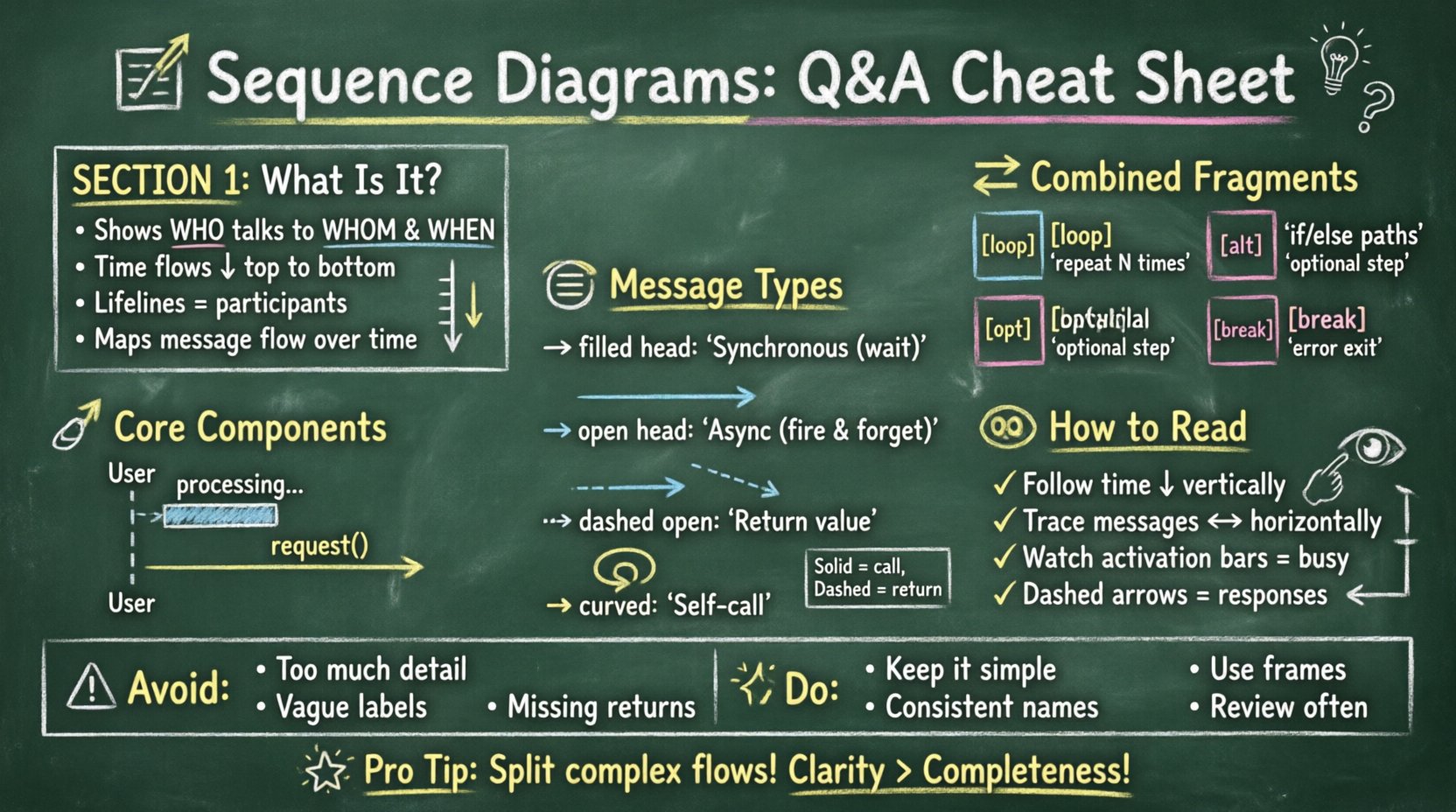
A sequence diagram is a type of interaction diagram that shows how operations are carried out. It captures the interaction between objects in the context of a collaboration. Unlike a class diagram that focuses on static structure, a sequence diagram focuses on dynamic behavior.
- Primary Purpose: To visualize the flow of messages between objects or systems.
- Time Axis: Time flows vertically from top to bottom.
- Participants: Objects, actors, or systems are represented as lifelines.
- Focus: It answers the question: “Who talks to whom, and in what order?”
This notation is essential during the analysis phase of the software development lifecycle. It helps stakeholders understand the logic before writing a single line of code. By mapping out the steps, teams can identify missing error handling or circular dependencies early in the design process.
2. What Are the Core Components of a Sequence Diagram? 🔧
Understanding the syntax is the first step toward creating or reading these diagrams effectively. Every diagram consists of a set of standard elements that convey specific meanings.
Lifelines
A lifeline represents a participant in the interaction. It is drawn as a vertical dashed line. The top of the line contains the name of the participant. This could be a class instance, a database, a user, or an external service. If a participant appears multiple times, it usually indicates different instances or states of the same entity.
Activation Bars
Also known as execution occurrences, these are thin rectangles placed on the lifeline. They indicate the period during which the participant is performing an action or waiting for a response. A long activation bar suggests a complex process or a wait time. A short one implies a quick method call.
Messages
Messages are horizontal arrows connecting lifelines. They represent communication between participants. The arrow direction indicates the sender and receiver. Different line styles denote different types of communication, such as synchronous calls or asynchronous events.
3. How Do You Distinguish Between Message Types? 📩
The style of the arrow tells the story of the interaction. Knowing the difference is crucial for accurate modeling.
- Synchronous Messages: Represented by a solid line with a filled arrowhead. The sender waits for the receiver to complete the action before proceeding. This is the most common type in method calls.
- Asynchronous Messages: Represented by a solid line with an open arrowhead. The sender sends the message and continues without waiting for a response. This is common in event-driven systems.
- Return Messages: Represented by a dashed line with an open arrowhead. This indicates the response coming back from the receiver to the sender.
- Self-Messages: Represented by a curved arrow pointing back to the same lifeline. This indicates an object calling a method on itself.
| Message Type | Arrow Style | Behavior | Use Case |
|---|---|---|---|
| Synchronous | Solid, Filled Head | Block until response | Method calls requiring data |
| Asynchronous | Solid, Open Head | Non-blocking | Event notifications |
| Return | Dashed, Open Head | Response flow | Data return |
| Self-Call | Curved Arrow | Internal processing | Recursive functions |
4. What Are Combined Fragments? 🔄
Real-world logic often involves conditions and loops. Combined fragments allow you to group interactions that occur under specific circumstances. These are enclosed in a frame labeled with a keyword.
Loop
The loop frame indicates that the enclosed interaction happens repeatedly. It is often used for processing collections or iterating through a list. You can specify the number of iterations or a condition within the frame.
Alt (Alternative)
The alt frame represents conditional logic, similar to an if-else statement. It divides the interaction into different paths based on boolean conditions. Only one path is taken during execution. This is vital for showing error handling or different user choices.
Opt (Optional)
The opt frame indicates that the enclosed interaction may or may not occur. It is used when a specific condition is not mandatory but possible. This helps in modeling optional features or non-critical flows.
Break
The break frame is used when an exception or error condition stops the normal flow. It shows that if a specific condition is met, the subsequent interactions are skipped.
5. How Do You Read a Sequence Diagram? 👀
Reading these diagrams requires scanning from top to bottom and left to right. Start with the initiating actor or object. Follow the arrows down the lifelines.
- Top-Down Flow: Always follow the vertical axis for time progression.
- Left-to-Right Logic: Observe the horizontal movement for message direction.
- Check Activation: Look at the activation bars to see who is busy. If a lifeline has no activation, the object is idle.
- Trace Returns: Follow dashed lines back up to ensure every call has a response.
Clarity is key. If a diagram is too crowded, it becomes unreadable. It is often better to split complex flows into multiple diagrams rather than cramming everything into one.
6. Sequence Diagram vs. Class Diagram 🆚
Confusion often arises between sequence diagrams and class diagrams. While both are part of UML, they serve different purposes.
| Feature | Sequence Diagram | Class Diagram |
|---|---|---|
| Focus | Behavior over time | Structure and attributes |
| Participants | Instances/Objects | Classes/Types |
| Time | Explicit (Vertical axis) | None |
| Usage | Designing workflows | Defining schema |
Use a class diagram to define what objects exist and how they relate structurally. Use a sequence diagram to define how those objects behave during a specific use case. They complement each other rather than compete.
7. What Are Common Mistakes to Avoid? ⚠️
Creating these diagrams is straightforward, but making them useful requires discipline. Several pitfalls frequently undermine the value of the model.
- Too Much Detail: Including every single getter and setter clutters the diagram. Focus on the business logic and critical interactions.
- Ambiguous Labels: Naming messages without context makes them hard to understand. Use verb-noun pairs (e.g.,
fetchUserinstead ofget). - Ignoring Returns: Forgetting return arrows makes the flow look incomplete, especially in synchronous interactions.
- Mixing Layers: Keep the diagram focused. Do not mix database persistence logic with user interface logic in the same view unless necessary.
- Unlabeled Lifelines: Every participant should have a clear name. Generic labels like “System” are often too vague.
8. How Do You Handle Error Scenarios? 🚨
Robust systems must handle failures. Sequence diagrams are excellent for visualizing these paths.
- Exception Frames: Use the
breakfragment to show where an error stops the process. - Error Messages: Explicitly label return messages that indicate failure (e.g.,
500 ErrororNullReference). - Recovery Logic: Show retry mechanisms or fallback paths using
altfragments. - Timeouts: Indicate when a message takes too long and the system gives up.
By modeling the happy path and the sad path, you ensure the design accounts for reality. This reduces bugs in the implementation phase.
9. When Is the Best Time to Create Them? 🗓️
Timing matters. Creating these diagrams too early or too late can lead to rework.
- Requirement Analysis: Use them to clarify user stories and workflows with stakeholders.
- System Design: Use them to plan API contracts and microservice communication.
- Code Review: Use them to verify that the implementation matches the intended design.
- Documentation: Use them for onboarding new developers to understand system flow.
They are most valuable when the logic is complex and hard to describe in text alone. Simple flows might not need a full diagram, but complex integrations do.
10. What Are the Best Practices for Clarity? ✨
To ensure your diagrams serve their purpose, adhere to these guidelines.
- Keep it Simple: Avoid unnecessary complexity. If a diagram has ten lifelines, consider splitting it.
- Consistent Naming: Use the same terminology for objects across all diagrams.
- Logical Grouping: Group related messages together. Don’t scatter interactions randomly.
- Use Frames: Always use combined fragments for loops and conditions to make logic explicit.
- Review Regularly: Treat the diagram as a living document. Update it when the logic changes.
11. Can Sequence Diagrams Be Used for Non-Software Systems? 🌐
Yes. While primarily used in software engineering, the notation applies to any process with steps and actors.
- Business Processes: Map out interactions between departments.
- Hardware Systems: Model communication between sensors and controllers.
- API Integrations: Define data exchange between third-party services.
The concept of message passing over time is universal. Adapting the notation to these contexts can improve cross-functional understanding.
12. How Do You Ensure Accuracy in Modeling? ✅
Accuracy depends on validation. Once the diagram is drawn, it must be verified.
- Walkthroughs: Walk through the diagram with a developer to check feasibility.
- Test Case Alignment: Ensure the diagram covers the scenarios defined in test cases.
- Peer Review: Have another team member review the notation for errors.
- Traceability: Link the diagram back to the specific requirement or user story.
Validation ensures the model is not just a drawing, but a reliable blueprint for development.
Summary of Key Takeaways 📝
Sequence diagrams are a powerful tool for visualizing system interactions. They provide a temporal view of how objects communicate, making complex logic easier to grasp. By understanding the core components, message types, and control structures, teams can design more robust systems.
Remember to avoid clutter, focus on the critical paths, and update the diagrams as the system evolves. They are not just documentation; they are a communication bridge between design and implementation.
Frequently Asked Technical Details ❓
Does the order of lifelines matter?
The horizontal position does not imply priority. Lifelines can be rearranged for clarity. The vertical order defines the time sequence.
Can you show multiple threads?
Yes, you can use threads to indicate parallel processing. This is often shown by splitting a lifeline or using specific notation for concurrent tasks.
What happens if a message is lost?
In a standard sequence diagram, messages are assumed to be delivered unless specified otherwise. If loss is possible (e.g., in unreliable networks), you should explicitly model the retry or error path.
Final Thoughts on Interaction Modeling 🎯
Mastering these diagrams takes practice. Start with simple flows and gradually add complexity. The goal is not perfection in the drawing, but clarity in the understanding. When a diagram can be read by a new team member without explanation, it has succeeded.
Investing time in these models pays off during maintenance and debugging. It provides a reference point when questions arise about how the system behaves. In the end, clear design leads to cleaner code.
