


In the complex ecosystem of software architecture, visual communication serves as the bridge between abstract logic and concrete implementation. Sequence diagrams are a fundamental tool in this process, detailing the interactions between objects or systems over time. However, a diagram that is visually cluttered or semantically ambiguous defeats its purpose. It becomes noise rather than signal. To maintain clarity, ensure scalability, and facilitate effective collaboration, adherence to established industry standards is not optional—it is essential.
This guide provides a comprehensive framework for validating your sequence diagrams. We will explore the structural requirements, semantic rules, and presentation norms that define professional-grade documentation. By following this checklist, teams can reduce misinterpretation risks, streamline code reviews, and maintain a consistent documentation ecosystem across the organization.
🏗️ Why Standardization Matters in System Design
Software development is rarely a solitary endeavor. It involves architects, backend engineers, frontend developers, QA specialists, and product managers. Each role interprets system behavior differently. A sequence diagram acts as a contract for these interactions. When standards are inconsistent, the contract becomes ambiguous.
Consider a distributed microservices environment. If one team documents a synchronous call while another documents an asynchronous event for the same interface, the integration fails. Standardization eliminates this friction. It ensures that a diagram created by a developer in one region is immediately understandable by an engineer in another.
Beyond communication, standards impact maintenance. Legacy systems require refactoring. If the documentation does not reflect the implementation, refactoring becomes a guessing game. Adhering to UML (Unified Modeling Language) specifications ensures that the diagrams remain valid even as the underlying technology evolves. This consistency supports long-term technical debt reduction.
Consistency: Reduces cognitive load for readers who encounter familiar patterns.
Accuracy: Aligns documentation with the actual flow of control and data.
Efficiency: Speeds up onboarding for new team members.
Automation: Standardized formats allow for better tooling integration and analysis.
📐 Core UML Principles for Interaction Modeling
Before diving into the specific checklist items, it is crucial to understand the foundational principles of the Unified Modeling Language. Sequence diagrams are part of the Interaction Diagram family. They focus on time and order. Unlike class diagrams, which describe structure, sequence diagrams describe behavior.
When creating these diagrams, you must strictly adhere to the notation rules defined in the UML 2.x specification. Deviating from these rules creates ambiguity. For example, the shape of a message arrow indicates the type of interaction. A solid line with a filled arrowhead implies a synchronous call. A dashed line with an open arrowhead implies a return message. Using a solid line for a return message misrepresents the timing and control flow.
Furthermore, the concept of a “lifeline” is central. A lifeline represents an instance of a class or participant over a period. It is not merely a vertical line; it is a timeline. The activation bar on the lifeline indicates the period during which the object is performing an action. If an object is merely waiting for a response, the activation bar should end before the return message arrives. This distinction helps in identifying bottlenecks in performance.
✅ The Comprehensive Validation Checklist
Validation should occur at multiple stages: during the design phase, before code implementation, and during the code review process. The following table outlines the critical checkpoints. Each item represents a requirement that must be met to consider the diagram compliant with industry standards.
Category | Check Item | Standard Requirement | Priority |
|---|---|---|---|
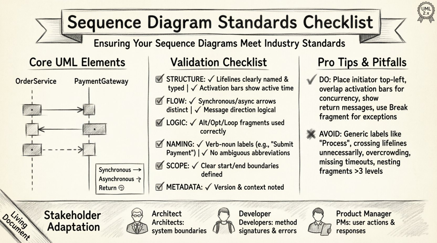
Structure | Lifeline Identification | All participants must be clearly named and typed. | High |
Structure | Activation Bars | Must reflect active processing time accurately. | High |
Flow | Message Direction | Synchronous vs. Asynchronous arrows must be distinct. | High |
Logic | Combined Fragments | Use alt, opt, loop correctly to denote logic. | Medium |
Naming | Label Clarity | Messages must describe action, not just data. | High |
Scope | Boundary Limits | Diagram must define start and end points. | Medium |
Metadata | Versioning & Context | Diagram must indicate version and system context. | Medium |
Let us examine these categories in detail to understand the implications of non-compliance.
1. Structural Integrity and Lifelines
Every sequence diagram must begin with a clear definition of the participants. A lifeline should not be a generic “System” or “User.” It should be specific, such as “OrderService” or “PaymentGateway.” This specificity prevents confusion when multiple services interact.
The vertical axis represents time. The top of the diagram is the earliest point in time, and the bottom is the latest. Do not cross lifelines unnecessarily. If lifelines cross, it implies a change in control flow that might be unintended. Use a frame or box to group related interactions if the scope is large.
Ensure every participant has a unique identifier within the diagram scope.
Do not reuse lifelines for different logical entities unless explicitly representing a polymorphic relationship.
Place the initiator of the interaction at the top or far left to establish context immediately.
2. Activation Bars and Control Flow
The activation bar (or execution occurrence) is a rectangle placed on the lifeline. It signifies that the object is active. Many diagrams omit this or place it incorrectly.
If Object A calls Object B, Object B’s activation bar starts when the message arrow touches the lifeline. It ends when the activation bar is returned to, or when the message leaves.
Incorrect placement leads to misinterpretation of concurrency. If you want to show that two objects are processing simultaneously, their activation bars should overlap horizontally. If they do not overlap, it implies sequential execution. This distinction is vital for performance analysis.
3. Message Types and Timing
Not all messages are created equal. The arrow style defines the timing.
Synchronous Call: The sender waits for the receiver to complete the task. Represented by a solid line with a filled arrowhead.
Asynchronous Call: The sender sends the message and continues without waiting. Represented by a solid line with an open arrowhead.
Return Message: The receiver sends data back to the sender. Represented by a dashed line with an open arrowhead.
Self-Call: An object calls a method on itself. The arrow loops back to the same lifeline.
Using a dashed line for a call implies that the message has already been sent, which contradicts the flow of a request-response model. Consistency in arrow types prevents developers from assuming blocking behavior where none exists.
4. Combined Fragments and Logic Blocks
Real-world logic is rarely linear. It involves conditions, loops, and parallel processing. UML supports this through Combined Fragments. These are frames that surround a group of messages.
Alt (Alternative): Use this for if-else logic. Ensure every alternative path is accounted for. Do not leave the “else” state undefined unless it is a known error state.
Loop: Use this for iteration. Label the loop condition clearly (e.g., “while items < 100”).
Opt (Optional): Use this for scenarios that may or may not occur, such as a cache hit.
Par (Parallel): Use this for concurrent processing. Ensure the start and end markers align correctly to show where concurrency begins and ends.
Break: Use this to indicate a specific path that exits the normal flow, such as an exception handler.
A common error is nesting fragments too deeply. Three levels of nesting is usually the maximum for readability. If you need more, consider splitting the diagram into sub-scenarios.
🔄 Deep Dive: Message Types and Flow Control
The flow of control is the narrative of the sequence diagram. It tells the story of how data moves through the system. Ambiguity here leads to race conditions or lost messages in the implementation.
Consider the distinction between a command and a query. A command changes state. A query retrieves state. Visually, these should not be distinguished unless the tool allows it, but semantically, they must be clear. If a diagram shows a query causing a side effect, that is a violation of the Command-Query Separation principle, and the diagram should reflect the correct pattern.
Another critical aspect is the handling of exceptions. In many diagrams, exceptions are hidden. They appear only when things go wrong. However, a robust diagram shows the failure path. If a database connection fails, does the system retry? Does it return a 500 error? Does it trigger a fallback service? This information belongs in the “Break” or “Alt” fragment.
Timeouts are also a part of flow control. If a call takes too long, the system must react. Indicate timeouts using a dashed line with a label specifying the duration (e.g., “Timeout: 5s”). This informs the developer of the expected latency constraints.
🔗 Handling Complexity: Fragments and Logic Blocks
As systems grow, diagrams become complex. To manage this, modularization is key. Do not try to show the entire system lifecycle in one diagram.
High-Level vs. Low-Level: A high-level diagram shows the flow between major subsystems. A low-level diagram details the logic within a single service. Both are needed, but they serve different audiences. The high-level diagram is for architects; the low-level diagram is for implementers.
Reference Frames: If a complex fragment is used in multiple diagrams, consider referencing it. Instead of repeating the logic, use a frame labeled “See Diagram X.” This reduces redundancy and ensures that changes to the logic are reflected across the documentation.
State Representation: Sometimes, the state of an object matters. While sequence diagrams are primarily interaction-focused, you can include notes to indicate state changes. For example, “Order Status: Pending -> Paid.” This helps in understanding the lifecycle of the data.
🏷️ Naming Conventions and Labeling Standards
Text on a diagram is often read more often than the graphics. Poor naming makes the diagram useless.
Verb-Noun Structure: Message labels should follow a verb-noun pattern. “GetOrder” is better than “Order.” “SubmitPayment” is better than “Pay.” This implies action and intent.
Avoid Abbreviations: Do not use “usr,” “svc,” or “db” unless they are universally understood in your specific domain. Use “User,” “Service,” and “Database.” If a domain-specific acronym is necessary, define it in a legend.
Data Types: If the payload is critical, include it in the label. “Order(id: 123)” is more informative than “GetOrder.” This helps in understanding the interface contract without reading the code.
Case Sensitivity: Stick to a consistent casing convention. CamelCase is standard for method names. PascalCase is often used for class names. Do not mix them within the same diagram.
🏛️ Integration with System Architecture
Sequence diagrams do not exist in a vacuum. They are part of a larger documentation ecosystem.
Consistency with Class Diagrams: The objects in the sequence diagram must exist in the class diagram. If you reference a “CreditCardValidator” class in a sequence diagram, that class must be defined in the structural model. This linkage ensures that the design is traceable.
Consistency with API Contracts: The message names and parameters should match the API specification (e.g., OpenAPI/Swagger). If the API says “POST /orders,” the diagram should show a message named “CreateOrder” or “POST /orders.” Discrepancies here cause implementation errors.
Deployment Context: If the system is distributed, indicate the deployment nodes. Show which lifelines reside on which server. This helps in understanding network latency and failure domains.
🔄 Maintenance and Version Control
A diagram is a living document. It must evolve with the code. Failing to update the diagram is worse than not having one, as it creates false confidence.
Change Logs: Maintain a history of changes. If a diagram is modified, note what changed and why. This is crucial for audits and debugging historical issues.
Review Cycles: Integrate diagram review into the Definition of Done (DoD). A pull request should not be merged if the architecture documentation is not updated to reflect the new logic.
Tooling Integration: Use tools that support version control. Store diagrams in the same repository as the code. This ensures that the diagram and the code are deployed together and that refactoring the code is accompanied by updating the diagram.
❌ Common Errors to Avoid
Even experienced engineers make mistakes. Recognizing common pitfalls helps prevent them.
Circular Dependencies: If Diagram A references Diagram B, and Diagram B references Diagram A, it creates a loop. Break the dependency by abstracting the shared logic into a third diagram or a high-level overview.
Missing Return Messages: Always show the return path. It is easy to forget, but it is essential for understanding the full call stack.
Overcrowding: If a diagram requires scrolling horizontally or vertically to see the whole flow, it is too complex. Split it.
Ignoring Time: Do not imply that two messages happen at the exact same instant unless they are truly parallel. Use spacing to indicate time gaps.
Generic Messages: Avoid “Process” or “Handle.” Be specific about what is being processed or handled.
👥 Reviewing Your Diagrams for Stakeholders
Finally, the audience matters. A diagram for a technical lead looks different from one for a product manager.
For Architects: Focus on system boundaries, integration points, and data flow. Use standard UML notation strictly.
For Developers: Focus on method signatures, error handling, and edge cases. Include payload details.
For Product Managers: Focus on user actions and system responses. Minimize technical jargon and activation bars. Use narrative frames instead of technical fragments.
Conduct a peer review session specifically for documentation. Ask a colleague to look at the diagram without reading the code. Can they explain what the system does just by looking at the visual flow? If they cannot, the diagram needs refinement.
🚀 Next Steps for Compliance
Implementing these standards requires a shift in culture. It is not enough to have a checklist; the team must value the documentation as much as the code. Start by auditing existing diagrams against this checklist. Identify the gaps. Create a style guide that enforces these rules. Train new hires on the importance of standardized modeling.
Regularly revisit the standards. As technology evolves, new interaction patterns emerge. The checklist should be a living document, updated to reflect new best practices. By committing to this process, you ensure that your sequence diagrams remain a reliable source of truth throughout the software lifecycle.
Adherence to these standards is a marker of engineering maturity. It demonstrates a commitment to clarity, precision, and long-term maintainability. In an industry where complexity is the enemy, clear diagrams are your greatest ally.