Legacy codebases often become intricate webs of dependencies that obscure the original design intent. Over time, technical debt accumulates, making modifications risky and time-consuming. To navigate this complexity, developers require a clear view of the internal structure of software components. This is where the UML Composite Structure Diagram (CSD) proves valuable. By visualizing the internal architecture, teams can identify structural bottlenecks and plan refactoring efforts with precision.
Refactoring is not merely about changing code syntax; it is about improving the internal design while preserving external behavior. A CSD provides the necessary granularity to see how parts collaborate within a classifier. This guide details how to leverage this modeling technique to modernize legacy systems effectively.
Understanding UML Composite Structure Diagrams 📐
A Composite Structure Diagram is a specialized type of diagram within the Unified Modeling Language (UML). Unlike a standard Class Diagram, which shows relationships between classes, a CSD exposes the internal structure of a specific classifier. It answers the question: What makes up this component, and how do they interact?
This diagram focuses on:
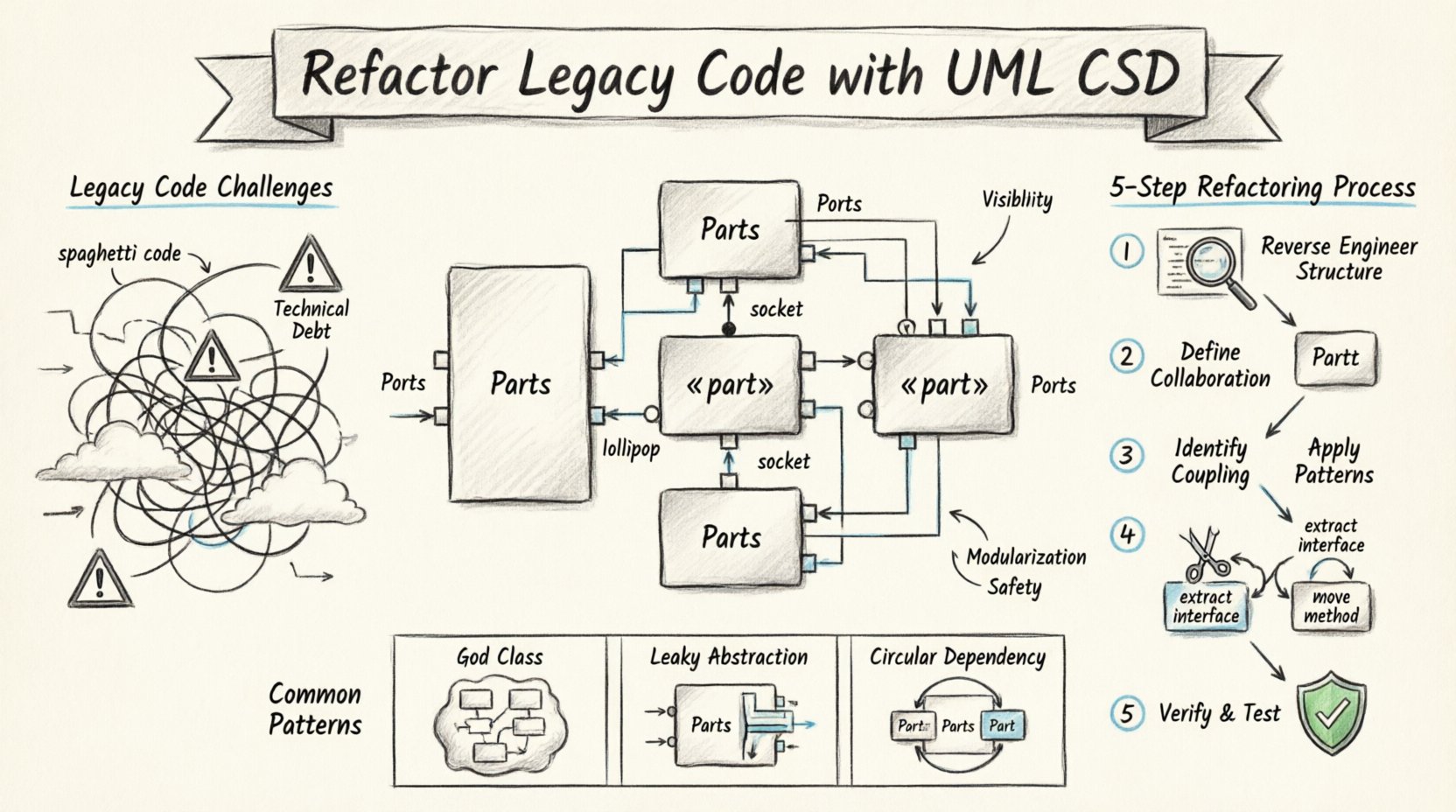
- Parts: The internal components that constitute the classifier.
- Roles: The interfaces that parts play within the structure.
- Ports: The interaction points where parts connect to the outside world or other parts.
- Connectors: The relationships that bind parts together, often defining data flow or control signals.
When applied to legacy code, the CSD acts as a reverse-engineered blueprint. It does not just show that Class A calls Class B; it reveals the specific context in which this interaction occurs. This visibility is critical for understanding boundaries and responsibilities.
Key Elements Explained
Before diving into the refactoring process, it is essential to understand the notation used in these diagrams.
- Parts: Represented as rectangles with the stereotype «part». A part has a type (the class) and a name (an instance identifier).
- Interfaces: Defined as lollipop symbols. Required interfaces are drawn as a ball on a stick (socket), while provided interfaces are a circle on a stick (lollipop).
- Collaboration: Shows how parts work together to fulfill the behavior of the composite.
- Internal Connections: Solid lines linking ports. These indicate direct communication pathways.
Why Use CSD for Legacy Refactoring? 🧩
Legacy systems often suffer from “spaghetti code,” where logic is scattered and dependencies are opaque. Standard class diagrams fail to capture the internal hierarchy of a complex component. A CSD addresses this gap.
Here are the primary reasons to adopt this modeling approach:
- Visibility of Hidden Dependencies: It reveals how internal parts rely on each other, which might be hidden in the source code.
- Identification of High Coupling: By mapping connections, you can spot parts that are overly dependent on others.
- Boundary Definition: It clarifies what belongs inside a component versus what belongs outside.
- Refactoring Safety: Understanding the internal structure allows for safer modifications without breaking external contracts.
Consider a legacy payment processing module. A class diagram might show a PaymentProcessor class. A CSD would show that this class is composed of a Validator part, a Gateway part, and a Logger part. This distinction changes how you approach optimization.
Step-by-Step Process for Refactoring 🛠️
Refactoring with CSDs requires a structured approach. The following steps outline a workflow to analyze, model, and modify legacy code.
Step 1: Reverse Engineering the Structure
The first phase involves extracting the internal architecture from the existing codebase.
- Identify the Target Classifier: Select the component that requires refactoring. This is often the one causing the most errors or confusion.
- Extract Parts: Analyze the fields and methods of the target class to identify internal components. If a class manages a list of objects, those objects might be parts.
- Map Interfaces: Determine which methods are public (provided) and which are internal (required).
- Document Ports: Define the specific entry and exit points for data and control.
This step creates the initial draft of the Composite Structure Diagram. It does not need to be perfect, but it must represent the current state accurately.
Step 2: Defining Internal Collaboration
Once the parts are identified, you must define how they collaborate. This involves analyzing the method calls within the class body.
- Analyze Method Flows: Trace the execution path from one part to another.
- Identify Connectors: Draw lines between parts to represent these flows. Label them to indicate the data type or signal passed.
- Check for Orphans: Ensure every part is connected. Isolated parts may indicate unused code or dead logic.
This visualization often reveals circular dependencies or redundant communication paths that were not obvious in the code.
Step 3: Identifying Coupling and Cohesion
With the diagram complete, you can assess the quality of the design. Use the following criteria to evaluate the structure:
| Metric | Description |
|---|---|
| Internal Coupling | How many parts depend on each other directly? |
| Interface Usage | Are interfaces reused or duplicated? |
| Port Granularity | Are ports too broad (do everything) or too narrow? |
| Data Flow | Is data passing through too many intermediate parts? |
High internal coupling suggests a need for modularization. If a part requires access to the internal state of another part without a defined interface, this indicates a violation of encapsulation.
Step 4: Applying Structural Refactoring Patterns
Based on the analysis, apply specific refactoring techniques. The CSD guides which parts need extraction or movement.
- Extract Interface: If a part is used by multiple other parts, define a common interface to reduce coupling.
- Move Method: If a method belongs logically to a part rather than the composite, move it.
- Replace Conditional Logic: If the structure relies on complex conditionals to route behavior, replace this with a Strategy pattern implemented via parts.
- Split Composite: If the composite class is doing too much, split it into smaller composites and link them via connectors.
Each change should be reflected in the diagram before code changes are made. This ensures the architectural intent is maintained.
Step 5: Verification and Testing
After refactoring, the diagram must match the code again. This ensures the design intent was preserved.
- Update the Diagram: Modify the CSD to reflect the new structure.
- Run Regression Tests: Ensure external behavior remains unchanged.
- Code Review: Have peers verify that the new structure aligns with the diagram.
Common Patterns and Scenarios 🚦
Certain architectural smells appear frequently in legacy code. The CSD helps identify and resolve them.
1. The God Class
A class that contains logic for multiple distinct responsibilities. A CSD reveals this by showing too many parts and connectors.
- Solution: Decompose the class into multiple composites.
- Visual Cue: A single rectangle with excessive internal ports.
2. The Leaky Abstraction
When internal implementation details are exposed to the outside world. In a CSD, this looks like internal parts having direct connections to external ports.
- Solution: Introduce a facade or adapter part to shield internal complexity.
- Visual Cue: Internal parts connecting directly to the boundary.
3. Tight Circular Dependency
Part A calls Part B, and Part B calls Part A. This creates a cycle that is hard to break.
- Solution: Introduce a mediator part or an event-based interface to decouple the interaction.
- Visual Cue: A closed loop of connectors between parts.
Challenges in Modeling Legacy Systems ⚠️
While CSDs are powerful, applying them to legacy code presents specific challenges.
- Lack of Documentation: Legacy systems often lack design docs. The diagram becomes the primary documentation.
- Implicit Knowledge: Developers may know how parts interact, but this is not explicit in the code.
- Time Constraints: Creating detailed diagrams takes time. Focus on high-risk areas first.
- Dynamic Behavior: Some legacy code relies on runtime reflection. Static diagrams may not capture all behaviors.
To mitigate these, use a layered approach. Start with a high-level CSD, then drill down into specific modules as needed.
Best Practices for Success ✅
To ensure the process is efficient and effective, adhere to the following guidelines.
- Start Small: Do not attempt to model the entire system at once. Focus on one problematic module.
- Keep it Updated: Treat the diagram as living documentation. Update it whenever the code changes significantly.
- Focus on Behavior: Don’t just draw boxes; document the data flow and control signals.
- Collaborate: Involve senior developers in the modeling process to validate assumptions.
- Automate Where Possible: Use tools that can generate diagrams from code to speed up the reverse engineering phase.
Integrating with Modern Architectures 🔄
Refactoring legacy code often aims to migrate towards modern architectures like microservices. The CSD serves as a bridge between monolithic legacy structures and distributed modern designs.
By isolating parts within a composite, you can identify which parts can be extracted into independent services. For example, if a ReportingPart has distinct ports and minimal dependencies on the DatabasePart, it might be a candidate for separation.
This structural clarity reduces the risk of migration. You know exactly what boundaries need to be crossed and what interfaces need to be exposed.
Conclusion on Structural Refactoring 📝
Refactoring legacy code is a delicate process that requires a deep understanding of the existing architecture. The UML Composite Structure Diagram provides the necessary lens to see internal complexities that standard diagrams hide. By mapping parts, roles, and connectors, teams can identify coupling issues, plan modularization, and execute changes with confidence.
While the process demands effort, the long-term benefits include reduced technical debt, improved maintainability, and a clearer path for future evolution. Use the diagram as a guide, not a constraint, and let the structure inform the code.

