Software architecture is often described in terms of components and their interactions. While standard class diagrams show static relationships, they often fail to reveal the internal composition of a complex classifier. This is where the UML Composite Structure Diagram becomes essential. It provides a detailed view of the internal structure of a classifier, showing how its parts interact to fulfill the system’s requirements.
This guide explores the mechanics of creating these diagrams. We will examine the core elements, notation, and practical applications. By the end, you will understand how to model complex nested structures without ambiguity.
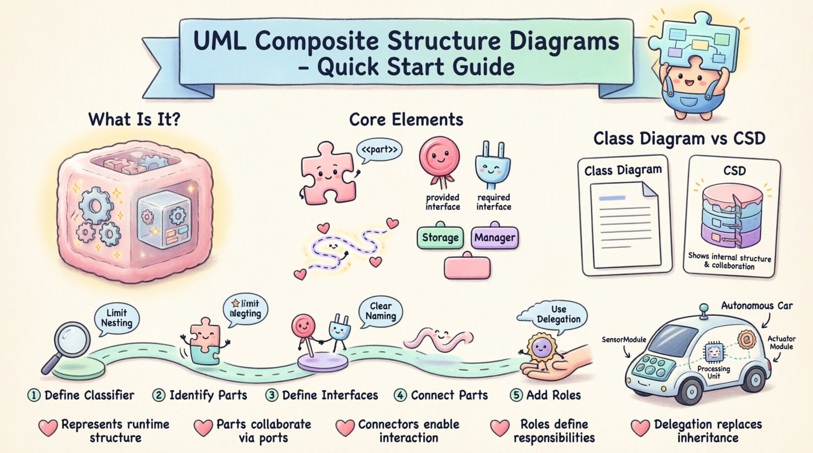
🧩 What Is a Composite Structure Diagram?
A Composite Structure Diagram (CSD) is a type of UML diagram that describes the internal structure of a classifier. It focuses on the parts that make up a whole and the interfaces those parts use to communicate. Unlike a Class Diagram, which focuses on attributes and operations, a CSD focuses on composition and interaction.
Think of a composite structure diagram as an X-ray of a software component. It reveals the machinery underneath the hood. This is particularly useful when dealing with:
- Complex nested structures
- Components with multiple interfaces
- Systems requiring strict boundary definitions
- Architectures that rely heavily on delegation and ports
The diagram allows architects to visualize how a system is built from smaller, reusable pieces. It clarifies the contract between the internal parts and the external environment.
🛠 Core Elements and Notation
To draw a valid UML Composite Structure Diagram, you must understand its building blocks. Each element has a specific purpose and visual representation.
1. Parts
A Part represents a piece of the classifier’s internal structure. It is an instance of a classifier that exists within the composite. Parts are named and typed.
- Visual: A rectangle with the stereotype <<part>> or simply the part name and type.
- Role: A part may play a specific role in the interaction.
- Visibility: Parts can be public, private, or protected.
2. Ports
Ports are the interaction points of a part or a classifier. They define how a part connects to the outside world or to other parts. A port encapsulates the interface a part provides or requires.
- Provided Interface: Denoted by a lollipop symbol, indicating functionality offered to the outside.
- Required Interface: Denoted by a socket symbol, indicating functionality needed from the outside.
- Directionality: Ports can be input, output, or both.
3. Roles
When a part connects to a connector, it does so under a specific role. The role defines how the part participates in the collaboration. For example, a database part might play the role of "Storage" while a controller part plays the role of "Manager".
4. Connectors
Connectors represent the links between parts or between a part and a port. They define the pathway for data or control flow.
- Binding Connector: Connects a provided interface to a required interface.
- Delegation Connector: Connects a port of a composite to a port of an internal part.
📊 Comparison: Class Diagram vs. Composite Structure Diagram
Understanding when to use a Composite Structure Diagram over a Class Diagram is critical for effective modeling. Below is a breakdown of the differences.
| Feature | Class Diagram | Composite Structure Diagram |
|---|---|---|
| Focus | Attributes and Operations | Internal Composition and Interaction |
| Granularity | Logical Structure | Physical or Logical Composition |
| Relationships | Association, Aggregation, Inheritance | Part, Port, Connector, Role |
| Complexity | Flat Structure | Nested Structure Support |
| Usage | General Data Modeling | Component Architecture Design |
Use a Class Diagram for general data relationships. Use a Composite Structure Diagram when the internal wiring of a component matters significantly to the system’s behavior.
🛤 Step-by-Step: Creating a Composite Structure Diagram
Follow this logical process to construct a diagram from scratch. This workflow ensures consistency and clarity.
Step 1: Define the Classifier
Start by identifying the classifier you want to analyze. This is usually a complex class or component that requires internal decomposition. Draw the main rectangle representing this classifier.
Step 2: Identify Internal Parts
Break down the classifier into its constituent parts. Ask yourself: What smaller components make up this system? List them as parts within the main rectangle. Assign types to each part.
Step 3: Define Interfaces
Determine what functionality each part exposes and what it requires. Draw lollipop symbols for provided interfaces and socket symbols for required interfaces on the relevant parts.
Step 4: Connect the Parts
Draw connectors between the parts. Ensure that every required interface is connected to a corresponding provided interface. Use delegation connectors if you need to expose internal functionality through the main classifier’s ports.
Step 5: Add Roles and Multiplicity
Label the ends of your connectors with roles. Specify multiplicity if a part can have multiple instances or relationships. This adds precision to the model.
💡 Practical Example: A Car Control System
Let us apply these concepts to a real-world scenario. Imagine modeling the control system of an autonomous vehicle.
- Classifier: VehicleControlSystem
- Parts:
- SensorModule (Type: SensorArray)
- ProcessingUnit (Type: CPU)
- ActuatorModule (Type: MotorController)
- Ports:
- SensorPort (Required: RawData)
- CommandPort (Provided: ControlSignal)
In this model:
- The SensorModule provides raw data. It is connected to the ProcessingUnit via a binding connector.
- The ProcessingUnit analyzes data and requires a control signal interface.
- The ActuatorModule provides the control signal. It connects to the ProcessingUnit.
- The VehicleControlSystem exposes a CommandPort that delegates to the ActuatorModule.
This structure shows how the external command flows through the internal processing to the physical actuators. It clarifies the data path without cluttering the high-level design.
🎯 Best Practices for Modeling
To maintain clarity and utility, adhere to these guidelines when drawing your diagrams.
- Limit Nesting Depth: Deeply nested structures become unreadable. If a part requires its own internal diagram, consider creating a separate diagram for it.
- Use Clear Naming: Avoid generic names like "Part1". Use descriptive names like "DatabaseConnector" or "UserInterface".
- Minimize Cross-Connections: Try to keep connectors local to the classifier. If a part connects to an external system, use a delegation connector to the main classifier’s port.
- Consistent Notation: Stick to standard UML symbols. Do not invent custom icons.
- Focus on Interaction: Do not model every attribute. Focus on the interfaces and connections that define behavior.
🔍 Common Pitfalls to Avoid
Even experienced modelers make mistakes. Here are common issues to watch out for.
- Confusing Ports with Interfaces: A port is a point of interaction; an interface is a contract. A port implements an interface.
- Overcomplicating the Diagram: If the diagram spans multiple pages, you likely have too many parts. Decompose the classifier.
- Missing Delegation: If an internal part provides a service needed by the outside, you must use a delegation connector to the main port.
- Ignoring Multiplicity: Failing to specify how many instances of a part exist can lead to implementation errors.
📈 When to Use This Diagram
Not every component needs a Composite Structure Diagram. Use it when:
- The internal wiring is complex and affects external behavior.
- You need to specify reuse of internal parts.
- You are defining strict boundaries for component deployment.
- You need to document delegation of interfaces.
For simple classes with straightforward attributes, a Class Diagram is sufficient. Reserve the Composite Structure Diagram for high-value architectural decisions.
🧠 Advanced Concepts
As you become more proficient, you can explore advanced features of the notation.
Proxy Ports
A Proxy Port acts as a placeholder for a part that is not yet implemented. It allows you to design the system flow before the component is built.
Value Specification
You can specify fixed values for certain attributes within the part definition. This is useful for configuration parameters.
Behavioral Protocols
Ports can be associated with state machines. This defines the sequence of interactions allowed on that port.
📝 Summary of Key Takeaways
To summarize the essential points for your design work:
- Composite Structure Diagrams reveal internal composition.
- Parts, Ports, Roles, and Connectors are the core elements.
- Differentiate clearly between Provided and Required interfaces.
- Use delegation connectors to expose internal functionality.
- Keep diagrams readable by avoiding excessive nesting.
- Validate your model against the system’s runtime behavior.
Mastering this diagram type adds depth to your architectural documentation. It bridges the gap between high-level design and low-level implementation details. By following these guidelines, you can create clear, maintainable models that serve your team effectively.
❓ Frequently Asked Questions
Can I combine a Class Diagram and a Composite Structure Diagram?
Yes. Use the Class Diagram for the overall data model and the Composite Structure Diagram for specific complex components. They complement each other.
Do I need to show every single method in a Composite Structure Diagram?
No. Focus on the interactions. Methods belong to the operations of the parts, not the structure itself.
What if I have multiple instances of a part?
Specify the multiplicity on the connector end. This indicates how many instances are required or allowed.
Is this diagram supported by all modeling tools?
Most modern modeling tools support standard UML notation, but some may have specific limitations on advanced features like nested composite structures.
🏁 Final Thoughts
Modeling software architecture is an exercise in clarity. The UML Composite Structure Diagram offers a powerful lens for examining how systems are assembled. By understanding parts, ports, and connections, you gain control over the complexity of your designs. Use this tool to document, communicate, and validate your architectural decisions. With practice, these diagrams become an integral part of your design workflow.

