Understanding the structural relationships within a software system is fundamental to robust architecture design. Among the various diagrammatic tools available in the Unified Modeling Language (UML), the Composite Structure Diagram offers a granular view of internal structures. Specifically, modeling aggregation correctly ensures that the lifecycle and ownership of components are clearly defined. This guide explores the mechanics of aggregation within this context, providing actionable steps for accurate representation.
When designing complex systems, distinguishing between different types of relationships is crucial. Aggregation represents a specific kind of association where one class holds a reference to another, but without strict ownership. This nuance impacts how data flows and how objects are destroyed. By mastering the visual notation and logical implications, architects can create diagrams that truly reflect system behavior.
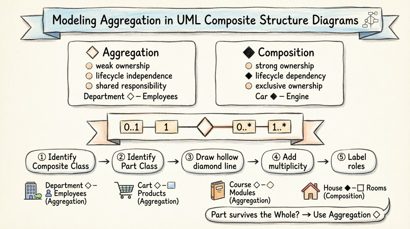
🔍 Understanding Composite Structure Diagrams
A Composite Structure Diagram focuses on the internal composition of a classifier. It shows how a class is built from its constituent parts. Unlike a standard Class Diagram which shows relationships between classes, this diagram zooms in on the internal arrangement. It highlights ports, interfaces, and connectors that allow interaction between parts.
Key elements include:
- Classifiers: The top-level containers defining the structure.
- Parts: Instances of other classifiers contained within the main classifier.
- Ports: Interaction points where parts connect to the outside world.
- Connectors: Links that establish communication pathways between parts.
Aggregation fits into this framework as a relationship between the composite classifier and its parts. It implies a “whole-part” relationship, but one that is not exclusive. The part can exist independently of the whole.
⚖️ Defining Aggregation vs. Composition
Confusion often arises between aggregation and composition. Both involve parts within a whole, but the lifecycle dependency differs. Understanding this distinction is vital for accurate modeling.
Aggregation Characteristics
- Weak Ownership: The part can exist without the whole.
- Lifecycle Independence: Destroying the composite does not destroy the part.
- Shared Responsibility: Multiple wholes might own the same part instance.
- Visual Notation: Typically represented by a hollow diamond on the composite side.
Composition Characteristics
- Strong Ownership: The part cannot exist without the whole.
- Lifecycle Dependency: Destroying the composite destroys the part.
- Exclusive Ownership: A part usually belongs to only one whole.
- Visual Notation: Typically represented by a filled diamond on the composite side.
When modeling aggregation, the goal is to show that the whole utilizes the part, but does not control its creation or destruction. For example, a Department aggregates Employees. If the Department is dissolved, the Employees still exist as individuals.
🎨 Visual Notation Rules in UML
Consistency in notation ensures that anyone reading the diagram understands the design intent immediately. The UML specification provides clear guidelines for representing aggregation.
1. The Diamond Symbol
Place a hollow diamond shape at the end of the association line connected to the composite class. This visually signals aggregation. Ensure the diamond is not filled, which would incorrectly imply composition.
2. Multiplicity
Define how many parts exist within the whole. Common multiplicity values include:
- 0..1: Optional part.
- 1: Exactly one part required.
- 0..*: Zero or more parts allowed.
- 1..*: One or more parts required.
3. Role Names
Label the ends of the association line to clarify the perspective of the relationship. The end near the part often gets a role name indicating how the part is viewed by the whole.
🛠️ Step-by-Step Modeling Process
Building an accurate diagram requires a systematic approach. Follow these steps to ensure clarity and correctness.
Step 1: Identify the Composite Class
Begin by defining the main class that acts as the container. This is the “Whole” in the relationship. Consider the scope of the system. Is this a high-level module or a specific component?
Step 2: Identify the Part Class
Determine what constitutes the internal structure. These are the “Parts.” Ask if these parts can logically exist outside the context of the whole. If yes, aggregation is likely the correct relationship.
Step 3: Define the Relationship
Draw a line connecting the Composite Class and the Part Class. Place the hollow diamond on the side of the Composite Class. This establishes the direction of the aggregation.
Step 4: Specify Multiplicity
Add multiplicity constraints to the ends of the line. This defines cardinality. For instance, a Library might have 1..* Books. A Book might have 0..1 ISBN.
Step 5: Add Roles and Associations
Label the roles. A Part might be referred to as a “Component” or “Module” within the context of the whole. Ensure these names are consistent across the documentation.
🔄 Managing Part Lifecycles
One of the most common errors in structural modeling is assuming lifecycle dependency where none exists. Aggregation explicitly decouples the lifecycle. When modeling, consider the following scenarios.
- Shared Instances: Can the same Part instance be passed to multiple Composite instances? If so, aggregation is the only valid choice.
- External Persistence: Does the Part data persist in a database after the Composite is removed? If yes, avoid composition.
- Reusability: Is the Part designed to be reused across different systems? Aggregation supports this flexibility.
Failure to respect lifecycle independence can lead to memory leaks or orphaned data in the actual implementation. The diagram should serve as a contract for the developers implementing the logic.
🔌 Interfaces and Ports
In Composite Structure Diagrams, interaction is often mediated through ports. Aggregation does not imply that the Part uses the whole’s interface directly, but it may provide services.
- Provided Interfaces: The Part might offer functionality that the Composite exposes to the outside.
- Required Interfaces: The Composite might need functionality from the Part to operate.
- Connectors: Use connectors to map required interfaces on the Composite to provided interfaces on the Part.
This layer of abstraction allows for swapping implementations. If the Part is an aggregation, it can be replaced with another class implementing the same interface without breaking the Composite’s internal logic.
🚫 Common Pitfalls and Best Practices
Even experienced architects can stumble when defining structural relationships. Review these common issues to avoid them.
Pitfall 1: Confusing Aggregation with Association
All aggregations are associations, but not all associations are aggregations. Aggregation implies a structural part-of relationship. A simple association might just mean two classes know about each other, without one containing the other.
Pitfall 2: Over-Modeling
Do not model every single relationship. Focus on the structural composition that defines the class behavior. Excessive detail can clutter the diagram and obscure the main architecture.
Pitfall 3: Ignoring Navigation
Aggregation implies navigation from the Whole to the Part. Ensure the code supports traversing from the Composite to the Part. If navigation is only possible the other way, the diagram is misleading.
📊 Comparison Table: Aggregation Scenarios
The following table summarizes when to use aggregation versus other relationships based on system behavior.
| Scenario | Relationship Type | Reasoning |
|---|---|---|
| Car has Engine | Composition | Engine is specific to the Car; removing Car removes Engine context. |
| Department has Employees | Aggregation | Employees exist independently; they can move to other departments. |
| Team has Members | Aggregation | Members belong to multiple teams or leave the team but remain users. |
| Order contains Items | Aggregation | Items might be returned to inventory or used in other orders. |
| House has Rooms | Composition | Rooms generally do not exist without the House structure. |
🧩 Real-World Application Scenarios
To solidify understanding, consider specific application domains where aggregation is critical.
1. Enterprise Resource Planning
In ERP systems, a Project aggregates Tasks. Tasks have their own lifecycle and can be reassigned. The Project aggregates them to manage scheduling, but destroying the Project does not erase the Task history.
2. E-Commerce Systems
A Shopping Cart aggregates Products. The Products exist in the catalog regardless of whether they are in the cart. The Cart manages the temporary collection, but does not own the product data.
3. Educational Management
A Course aggregates Modules. Modules are reusable assets. They can be part of multiple courses. The Course aggregates them to define the curriculum path.
📝 Implementation Considerations
When translating the diagram into code, aggregation translates to member variables or dependency injection. It does not require deep copying of the object. A reference or pointer is sufficient.
- Memory Management: Do not manually delete the part object when the composite is destroyed.
- Garbage Collection: The runtime environment handles the part’s lifecycle independently.
- Reference Counting: If using languages with reference counting, ensure the part is not freed while still referenced by other composites.
Documentation should explicitly state the aggregation contract. Developers need to know they cannot assume exclusive control over the part instance. This prevents logic errors in cleanup routines.
🔗 Conclusion on Structural Integrity
Accurate modeling of aggregation within UML Composite Structure Diagrams strengthens the design phase. It clarifies ownership boundaries and lifecycle expectations. By adhering to standard notation and avoiding common pitfalls, teams can ensure their architectural diagrams remain reliable blueprints for development.
Focus on the semantic meaning of the relationships. Does the part survive the whole? If yes, use aggregation. This simple question guides the structural integrity of the entire system design. Continuous review of these diagrams during the development cycle ensures alignment between the theoretical model and the implemented software.

