Software architecture is often the bridge between abstract business requirements and concrete implementation details. Without a clear map, development teams can easily lose direction, leading to technical debt and miscommunication. The C4 model provides a structured approach to documenting software architecture at different levels of abstraction. This guide explores each layer in detail, helping you create documentation that scales with your system and remains useful over time. 📝
Understanding the Philosophy Behind the Model 🧠
Why do we need multiple levels of diagrams? A single diagram rarely captures the complexity of a modern distributed system. Some stakeholders need to see the big picture, while others require granular details about specific components. The C4 model addresses this by offering four distinct levels of detail. Each level serves a specific audience and answers specific questions.
The core philosophy is simplicity and focus. Instead of overwhelming the reader with every detail at once, the model encourages starting high and drilling down only when necessary. This approach prevents documentation bloat and ensures that the right people see the right information at the right time. It shifts the focus from drawing pretty pictures to communicating design intent effectively. 🤝
Key Principles
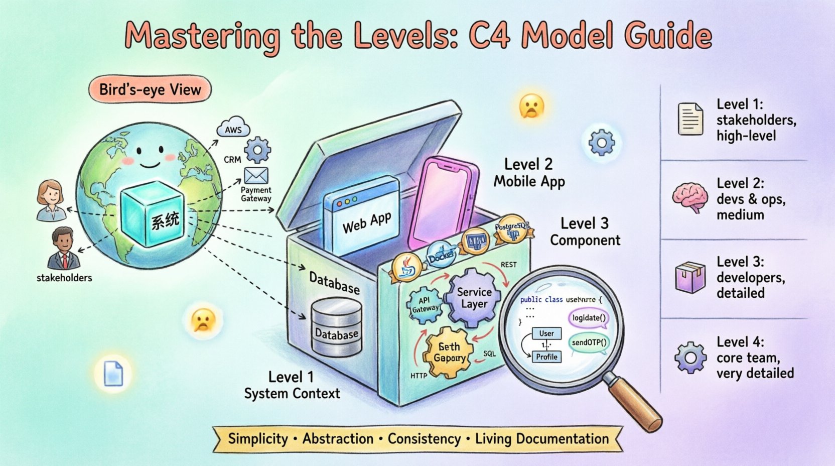
- Simplicity: Use simple shapes and lines to represent complex relationships.
- Abstraction: Each level hides unnecessary details from the previous level.
- Consistency: Maintain consistent naming conventions across all diagrams.
- Living Documentation: Keep diagrams up to date as the system evolves.
Level 1: System Context Diagram 🌍
The System Context diagram is the starting point for any architectural documentation. It provides a bird’s-eye view of the entire system and how it interacts with the outside world. This diagram is typically the first thing a new team member or stakeholder reviews to understand the scope of the application. 👀
Who Reads This?
- Business stakeholders and product owners
- New developers joining the team
- Security auditors
- System integrators
What Does It Show?
This diagram focuses on the system being designed and its external dependencies. It does not show internal structure. The key elements include:
- The System: Represented as a single box in the center.
- People: External users who interact with the system.
- Software Systems: Other applications or services that communicate with your system.
- Relationships: Lines connecting the system to external entities, labeled with the protocol or data flow.
Best Practices for Level 1
- Keep the diagram on a single page.
- Use clear labels for external systems; do not assume the reader knows them.
- Focus on the boundaries of your system, not the internals.
- Include the purpose of the system in the box label.
By defining the boundaries clearly, you set the stage for more detailed diagrams. This level answers the question: “What does this system do, and who does it talk to?” 🗺️
Level 2: Container Diagram 📦
Once the context is understood, the next step is to break down the system into its constituent containers. A container is a distinct unit of deployment and execution. This could be a web application, a mobile app, a database, or a microservice. 🛠️
Who Reads This?
- Development teams
- DevOps engineers
- System architects
- Infrastructure managers
What Does It Show?
The Container diagram zooms into the system box from Level 1. It reveals the high-level building blocks that make up the software. Key elements include:
- Containers: Boxes representing technologies like a web server, a database, or a queue.
- Technologies: Labels indicating the specific technology stack (e.g., Java, PostgreSQL, Docker).
- Connections: Lines showing how containers communicate, often specifying protocols like HTTP, TCP, or REST.
- People: Users interacting directly with specific containers.
Defining Containers
Identifying containers requires understanding your deployment architecture. Common examples include:
- Web Applications: Sites served to browsers.
- Mobile Applications: Apps running on phones or tablets.
- Databases: Persistent storage systems.
- Microservices: Independent services running in containers.
- Scripting Tools: Command-line utilities or background jobs.
This level answers the question: “What technologies are we using, and how are they connected?” 🔗
Level 3: Component Diagram ⚙️
For developers who need to understand the internal logic of a specific container, the Component diagram is essential. It breaks down a container into its major components. This is where the business logic and internal architecture become visible. 🧩
Who Reads This?
- Software developers
- Code reviewers
- Technical leads
What Does It Show?
A container is decomposed into components that work together to fulfill the container’s purpose. Components are not code files; they are logical groupings of functionality. Key elements include:
- Components: Subsystems within the container (e.g., Authentication, Data Access, API Gateway).
- Interfaces: Explicit points where components interact with each other.
- Relationships: Arrows showing data flow or dependency between components.
Identifying Components
Components should be cohesive and loosely coupled. When identifying them, consider:
- Functionality: What specific job does this part of the system do?
- Ownership: Who is responsible for maintaining this part?
- Independence: Can this part be changed without breaking others?
Example Structure
Imagine a web application container. Its components might include:
- Controller Layer: Handles incoming requests.
- Service Layer: Contains business rules.
- Repository Layer: Manages data persistence.
- Security Module: Handles authentication and authorization.
This level answers the question: “How is the internal logic organized within this technology?” 🏗️
Level 4: Code Diagram 💻
The Code diagram is the most detailed level. It maps components to actual source code structures, such as classes, interfaces, and functions. This level is often the most difficult to maintain and should be used selectively. 📜
Who Reads This?
- Senior developers
- Code auditors
- Onboarding specialists
When to Use Level 4
Because this level requires significant maintenance, it should not be used for every component. It is most valuable for:
- Complex algorithms that are hard to explain in code alone.
- Critical security paths that require strict verification.
- Legacy systems where the code structure is confusing.
Key Elements
- Classes: The fundamental building blocks of object-oriented code.
- Methods: Functions within classes.
- Relationships: Inheritance, composition, and dependency.
This level answers the question: “What does the implementation look like at the code level?” 🔍
Comparison of Levels 📊
To clarify the distinctions between the four levels, the following table summarizes their focus, audience, and typical usage.
| Level | Focus | Audience | Detail |
|---|---|---|---|
| Level 1 | System Boundary | Stakeholders | High |
| Level 2 | Technology Stack | Developers & Ops | Medium |
| Level 3 | Internal Logic | Developers | Low |
| Level 4 | Code Structure | Core Team | Very Low |
Maintaining and Evolving Documentation 🔄
Documentation becomes obsolete quickly if not maintained. The goal is to create a living artifact that evolves with the code. Here are strategies to keep your diagrams relevant.
Integration into Workflow
- Code Reviews: Require updates to diagrams alongside code changes.
- Automated Generation: Where possible, generate diagrams from code to reduce manual effort.
- Version Control: Store diagrams in the same repository as the source code.
- Ownership: Assign specific owners to specific diagrams.
Common Pitfalls ⚠️
Several mistakes can undermine the value of architectural documentation. Be aware of these common issues:
- Over-documentation: Creating diagrams for every minor change leads to noise.
- Inconsistency: Using different naming conventions across diagrams confuses readers.
- Outdated Info: Leaving diagrams unchanged after refactoring.
- Too Much Detail: Including internal implementation details where they are not needed.
Integrating into Dev Workflow 🛠️
Documentation should not be a separate activity. It must be woven into the daily routine of the engineering team. This ensures that the diagrams remain accurate without requiring a dedicated documentation sprint.
Practical Steps
- Start Small: Begin with Level 1 and Level 2. Add deeper levels as needed.
- Use Tools: Select generic diagramming tools that support version control.
- Review Regularly: Make diagram review a part of the sprint planning process.
- Feedback Loop: Encourage team members to suggest improvements to the visuals.
Conclusion on Documentation Strategy 📝
Creating a robust documentation strategy is about clarity and communication. By following the C4 model, you provide a clear path for stakeholders to understand your system. The model scales with your team size and system complexity. It avoids the trap of over-engineering documentation while ensuring that critical information is accessible. 🌟
Remember, the value of a diagram lies in its ability to convey meaning, not its aesthetic quality. Focus on the content, keep the levels distinct, and ensure your team agrees on the definitions. With consistent effort, your architectural documentation will become a valuable asset rather than a burden. 🚀

