When designing complex software systems, static class diagrams often reach their limit. They show how objects relate, but they do not reveal what lies inside a specific object. To understand internal behavior and interaction, architects move to a deeper level of abstraction. This is where the UML Composite Structure Diagram becomes essential. It bridges the gap between abstract classes and concrete internal implementations. 🏗️
This guide explores the mechanics of transitioning from standard class modeling to composite structure modeling. We will examine the specific elements, the logic behind the transition, and how to apply these diagrams to real-world architectural challenges.
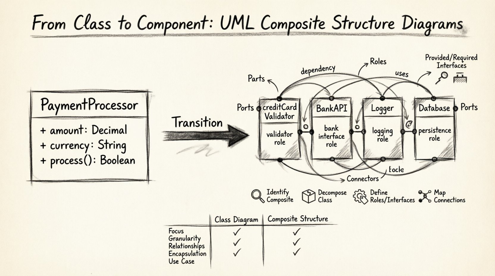
🏗️ Understanding the Shift: Why Move Beyond Classes?
Standard Class Diagrams are powerful for defining data structures and relationships. However, they treat a class as a black box. You know its attributes and methods, but you do not know how it is constructed from smaller pieces. The Composite Structure Diagram opens this box. It models the internal structure of a classifier.
Consider a scenario where a PaymentProcessor class exists. In a class diagram, this class might list methods like processTransaction(). But how does it achieve this? Does it delegate to a BankAPI? Does it use a Logger? Does it interact with a Database? The Class Diagram cannot show this wiring without clutter. The Composite Structure Diagram clarifies these dependencies.
- Visibility: It exposes internal parts and their connections.
- Interaction: It defines how parts communicate via ports and interfaces.
- Deployment: It helps visualize how components are assembled.
- Flexibility: It allows for modeling different configurations of the same class.
🧩 Core Elements of Composite Structure Diagrams
To build these diagrams effectively, one must understand the vocabulary of the UML 2.0 specification. Each element serves a specific purpose in defining the internal architecture.
1. Parts and Roles
A Part represents an instance of a classifier that is owned by a composite structure. Think of it as a component inside a larger machine. A part is not just a reference; it is a structural element. Associated with every part is a Role.
- Part: The specific instance (e.g.,
creditCardValidatorinsideCheckout). - Role: The name the part plays within the composite structure (e.g.,
validatorRole).
This distinction is vital. The same class can be used multiple times within a composite structure, each playing a different role. This allows for polymorphism and reuse within the internal wiring.
2. Ports and Interfaces
Parts need to talk to the outside world without breaking encapsulation. They do this through Ports. A port is a named point of interaction. It is not the part itself, but the interface through which the part communicates.
- Provided Interface: Services the part offers to others.
- Required Interface: Services the part needs from others.
Imagine a Microphone part inside a Phone structure. The Microphone part requires a SignalProcessor interface. It does not know which specific processor handles the signal, only that it needs that interface. This decoupling is the power of port-based modeling.
3. Connectors
Connectors link ports together. They define the flow of information. There are two main types of connections:
- Internal Connections: Links between ports within the same composite structure.
- External Connections: Links between a port on the composite structure and something outside of it.
Connectors ensure that data flows logically from a required interface to a provided interface. They form the circuitry of your software architecture.
🛠️ The Transition Process: From Class to Composite
Moving from a standard Class Diagram to a Composite Structure Diagram is a deliberate architectural step. It requires analysis of internal dependencies. Follow this logical progression to ensure accuracy.
Step 1: Identify the Composite
Start with the Class Diagram. Identify the class that requires internal decomposition. Look for classes with high complexity or multiple internal dependencies. These are prime candidates for composite structures.
Step 2: Decompose the Class
Break the class down into constituent parts. Ask these questions:
- Does this class contain other objects?
- Does it delegate responsibilities to other classes?
- Are there internal services that are hidden from the outside?
For each identified dependency, create a Part. Do not simply list them as associations. Define them as owned structural elements.
Step 3: Define Roles and Interfaces
Assign roles to each part. How does this part behave within the composite? Then, define the interfaces. What does this part require to function? What does it provide to the composite?
Step 4: Map the Connections
Draw the connectors. Link the required interfaces of one part to the provided interfaces of another. Ensure that the wiring reflects the actual flow of control or data. This step often reveals design flaws in the initial Class Diagram, such as circular dependencies or missing abstractions.
📊 Comparison: Class Diagram vs. Composite Structure Diagram
Understanding when to use which diagram is crucial. Confusing the two can lead to cluttered or ambiguous designs. The table below highlights the key differences.
| Feature | Class Diagram | Composite Structure Diagram |
|---|---|---|
| Focus | External relationships and attributes | Internal structure and composition |
| Granularity | High-level object definitions | Deep-dive into object internals |
| Relationships | Association, Inheritance, Aggregation | Parts, Roles, Ports, Connectors |
| Encapsulation | Implicit (via access modifiers) | Explicit (via Ports and Interfaces) |
| Use Case | Database schema, API contracts | Component architecture, Internal wiring |
Notice that the Class Diagram defines what an object is, while the Composite Structure Diagram defines how an object is built. Both are necessary for a complete architectural picture.
🌍 Real-World Scenarios and Examples
Abstract concepts become clearer when applied to specific domains. Let us examine how this transition works in practice.
Scenario 1: The E-Commerce Order System
In a basic class diagram, an Order class might have a list of OrderItem objects. However, an Order also needs to calculate totals, validate inventory, and process payments. A Composite Structure Diagram for the Order class would reveal:
- Part:
InventoryManager(Role: StockChecker) - Part:
PaymentGateway(Role: TransactionHandler) - Part:
TaxCalculator(Role: RateApplier)
Connectors would link the Order‘s internal interface for payment to the PaymentGateway part. This makes it clear that changing the payment provider only requires swapping the PaymentGateway part, not rewriting the entire Order class logic.
Scenario 2: The Data Processing Pipeline
Consider a data processing class. It receives raw data, cleans it, and stores it. A Class Diagram might show three methods. A Composite Structure Diagram shows three parts:
- Part:
DataIngestor - Part:
DataCleaner - Part:
DataStorer
Connectors flow from DataIngestor to DataCleaner, and then to DataStorer. This visualizes the pipeline. It also allows for parallel processing configurations by adding multiple DataCleaner parts connected to a load balancer interface.
⚠️ Common Pitfalls and Best Practices
Creating these diagrams can lead to complexity if not managed carefully. Avoid these common errors to maintain clarity.
1. Over-Modeling
Do not model every single attribute as a part. Only model parts that have significant behavior or interaction. If a class simply holds a string value, it does not need a composite structure. Reserve this diagram for complex internal logic.
2. Ignoring Interfaces
Ports without interfaces are meaningless. A port must specify what it provides or requires. If you draw a port but do not define the interface contract, the diagram loses its predictive value for implementation.
3. Mixing Levels of Abstraction
Do not mix components from different layers. A composite structure diagram should focus on the internal structure of a single classifier. Avoid trying to model the entire system architecture in one composite diagram. Use multiple diagrams for different classifiers.
4. Neglecting Multiplicity
Parts can have multiplicities. One Order might have many OrderItem parts. Specify these multiplicities on the part definition. This clarifies how many instances of a component are instantiated within the composite.
🔧 Advanced Concepts: Nested Structures
Composite structures can be nested. A part within a composite structure can itself be a composite structure. This allows for hierarchical modeling.
- Example: A
Servercomposite structure might contain aContainerpart. ThatContainerpart can have its own internal structure, showing its own parts and ports. - Benefit: This supports microservices architecture modeling. You can define the structure of a service, and the structure of the containers within it.
When modeling nested structures, use clear labeling. Ensure that the port names in the outer structure match the interface requirements of the inner structure. This consistency prevents integration errors during development.
📝 Implementation Considerations
While diagrams are design artifacts, they often influence code generation and documentation. When transitioning to composite structures:
- Code Organization: Map parts to separate classes or modules. This enforces the separation of concerns defined in the diagram.
- Dependency Injection: Use dependency injection frameworks to wire the parts together at runtime. The ports and interfaces define the injection contracts.
- Documentation: Use the diagram to generate API documentation. The provided interfaces become public APIs.
Remember that the diagram is a contract. If the code does not match the wiring in the diagram, the model is inaccurate. Regular refactoring is required to keep the visual model aligned with the codebase.
🚀 Future-Proofing Your Architecture
Software systems evolve. Requirements change, and new technologies emerge. The Composite Structure Diagram provides a flexible framework for adaptation.
- Swapping Parts: Because parts are connected via interfaces, you can replace a
Storagepart with aCloudStoragepart as long as they share the same interface contract. - Adding Features: You can add new parts without altering the external behavior of the composite, provided the new parts do not change existing interface contracts.
- Parallel Development: Different teams can work on different parts simultaneously. The ports define the boundaries, reducing merge conflicts.
This flexibility makes the Composite Structure Diagram a vital tool for long-term maintenance. It moves the design from a static snapshot to a dynamic blueprint of interaction.
🔍 Summary of Key Takeaways
The transition from Class Diagrams to Composite Structure Diagrams represents a maturation in software design. It moves the focus from what objects are to how they are constructed and connected.
- Parts represent internal instances of classifiers.
- Roles define the function of a part within the structure.
- Ports provide points of interaction via interfaces.
- Connectors define the flow of data between ports.
- Interfaces ensure loose coupling between components.
By adopting this modeling technique, architects gain visibility into the internal wiring of their systems. This visibility leads to more maintainable, scalable, and robust software. It is a step towards clarity in an increasingly complex digital landscape.
Start by identifying your most complex classes. Decompose them. Define their parts. Draw the connections. The resulting diagrams will serve as a reliable map for your development team, guiding the construction of your system from the inside out. 🚀

