System design requires precision. When multiple components interact to deliver a function, understanding the flow of control and data is critical. Sequence diagrams offer a visual narrative of this interaction over time. They are not merely drawings; they are specifications that define behavior, timing, and dependencies within a distributed system. This guide explores the mechanics, patterns, and best practices for constructing effective sequence diagrams.
📐 The Anatomy of a Sequence Diagram
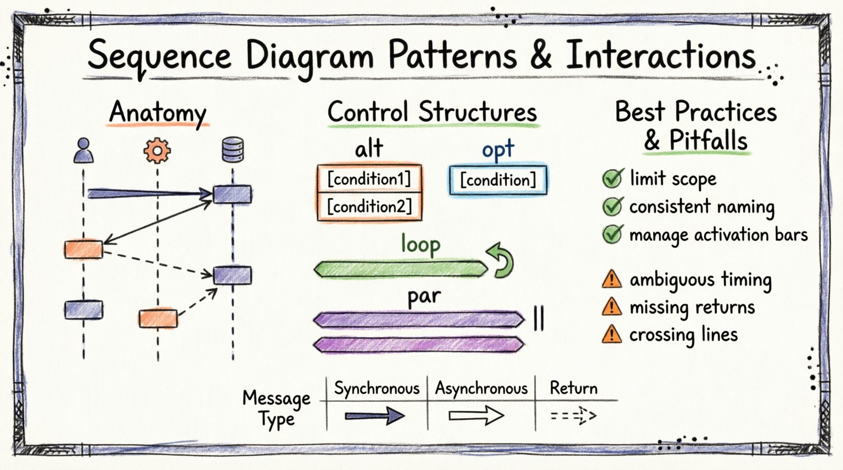
Before analyzing patterns, one must understand the building blocks. A sequence diagram visualizes how objects communicate with one another. It is organized vertically to represent time flowing downwards and horizontally to represent different participants.
Key Components
- Lifelines: Vertical dotted lines representing an object, actor, or system component. They signify the existence of the participant throughout the interaction.
- Activation Bars: Rectangular boxes on a lifeline indicating when the participant is actively performing a task. This helps visualize blocking and non-blocking operations.
- Messages: Arrows connecting lifelines. They represent communication between participants. The direction and style of the arrow convey the type of interaction.
- Return Messages: Dashed arrows indicating a response or return value from the receiver back to the sender.
Clarity in these elements ensures that developers and stakeholders can trace the execution path without ambiguity. Misplaced activation bars or unclear message types can lead to implementation errors later in the development cycle.
🔗 Types of Message Interactions
The semantics of a message define how the sender expects the receiver to behave. Choosing the correct message type is fundamental to accurate modeling.
1. Synchronous Messages
A synchronous message implies that the sender waits for the receiver to complete the operation before continuing. This is the standard request-response pattern.
- Visual Representation: Solid line with a filled arrowhead.
- Behavior: The sender blocks. Execution pauses until the response is received.
- Use Case: Database queries, API calls where the result is immediately required.
2. Asynchronous Messages
Asynchronous communication allows the sender to continue processing without waiting for the receiver to finish. The message is placed in a queue or sent via an event bus.
- Visual Representation: Solid line with an open (hollow) arrowhead.
- Behavior: The sender does not block. It proceeds to the next instruction immediately.
- Use Case: Logging events, sending notifications, background data processing.
3. Create and Destroy Messages
Lifelines are dynamic. Objects are created at runtime and destroyed when no longer needed. Diagrams must reflect this lifecycle.
- Creation: Represented by a specific message type indicating instantiation. The target lifeline begins at the point of creation.
- Destruction: Marked with an ‘X’ at the bottom of the lifeline. This indicates the object is removed from memory or the system context.
🔄 Control Structures and Interaction Patterns
Real-world systems rarely follow a single straight path. Conditional logic, loops, and parallel processes are common. Sequence diagrams use combined fragments to model these complex behaviors.
1. Alt (Alternative) Fragment
The alt fragment represents conditional logic. It is used when the flow of the diagram depends on a specific condition being met.
- Structure: A box with an orange border labeled
alt. It is divided into operands separated by a horizontal dashed line. - Operands: Each section represents a possible path. For example,
[user is authenticated]vs[user is not authenticated]. - Best Practice: Ensure all possible logical paths are covered. Missing an operand can hide potential error states.
2. Opt (Optional) Fragment
The opt fragment models optional behavior. The enclosed interactions occur only if a specific condition is true. If false, the fragment is skipped entirely.
- Structure: Similar to
alt, but typically contains a single operand labeled with the condition. - Use Case: Applying optional caching, showing a tooltip, or enabling a feature flag.
3. Loop Fragment
When an operation repeats, a loop fragment is used. This avoids drawing the same sequence multiple times, which creates clutter and reduces readability.
- Structure: A box labeled
loop. It can include a condition for termination. - Iterative Logic: Useful for processing lists, iterating through a collection of items, or retrying a failed network request.
- Refinement: You can specify the number of iterations or the condition (e.g.,
while (items not empty)).
4. Par (Parallel) Fragment
Complex systems often perform multiple tasks simultaneously. The par fragment indicates that the enclosed interactions occur concurrently.
- Structure: A box labeled
parcontaining multiple operands. - Concurrency: Indicates independent threads of execution. This is vital for performance modeling.
- Consideration: Parallel processes can introduce race conditions. The diagram should highlight where synchronization is required.
📊 Message Semantics Comparison
The following table summarizes the key differences between message types to aid in quick reference.
| Message Type | Arrow Style | Sender State | Common Use |
|---|---|---|---|
| Synchronous | Filled Arrowhead | Blocked / Waiting | Get Data, Update Record |
| Asynchronous | Open Arrowhead | Non-Blocking | Fire and Forget, Event Trigger |
| Return | Dashed Line | Response Flow | Return Value, Acknowledgement |
| Self-Message | Curved Arrow | Internal Processing | Method Call on Same Object |
🔍 Advanced Interaction Patterns
Beyond basic messages and fragments, specific patterns emerge in large-scale architectures. Understanding these helps in scaling design documentation.
1. Ref (Reference) Fragment
When a sequence becomes too complex, it is often split. The ref fragment refers to another sequence diagram that details the nested interaction.
- Benefit: Reduces cognitive load. It keeps the high-level diagram clean while allowing deep dives into specific modules.
- Implementation: Enclose the complex section in a box labeled
refwith a reference ID. The referenced diagram should share the same ID.
2. Critical (Crit) Fragment
Some interactions require strict execution constraints. The crit fragment indicates that the enclosed operations must complete without interruption.
- Context: Often used for transactional integrity or locking mechanisms.
- Implication: Other processes may be blocked or queued until the critical section is complete.
3. Break Fragment
The break fragment is used to describe a specific path where the normal flow is interrupted. This is distinct from alt because it represents an exception or a deviation rather than a standard conditional branch.
- Scenario: A timeout occurs, or a system error forces an exit from the standard loop.
- Labeling: Clearly label the condition, such as
[system failure].
🛠️ Best Practices for Modeling
Creating a diagram is easy; creating a useful one requires discipline. Adhering to established guidelines ensures the artifact serves its purpose effectively.
1. Limit Scope per Diagram
A single diagram should focus on a specific use case or a coherent set of operations. Avoid combining unrelated flows. If a diagram spans too many actors or extends vertically for pages, it loses value.
- Strategy: Break complex flows into User Login, Search Item, and Process Payment as separate diagrams.
- Navigation: Use
reffragments to link related diagrams together.
2. Consistent Naming Conventions
Labels must be descriptive. Generic names like send or process provide little context. Use verbs that describe the business action.
- Good:
validateUserCredentials,fetchInventoryStock. - Bad:
check,get.
3. Manage Activation Bars
Do not clutter the diagram with unnecessary activation bars. Only show activation when the participant is actively processing. If a participant is waiting passively, the activation bar should end before the wait begins.
- Clarity: This highlights bottlenecks. Long activation bars indicate heavy processing or blocking I/O.
4. Avoid Over-Engineering
Not every interaction needs a sequence diagram. Use them for critical flows, complex logic, or integration points. Simple CRUD operations often do not warrant this level of documentation.
🚫 Common Pitfalls to Avoid
Even experienced modelers make mistakes. Recognizing these common errors helps maintain diagram quality.
- Ambiguous Timing: Sequence diagrams imply time, but they do not always specify exact timestamps. Avoid implying strict time limits unless using timing diagrams.
- Missing Return Messages: If a synchronous message is sent, a return message should generally be shown, even if it is empty. This confirms the handshake.
- Crossing Lines: Try to arrange participants so message lines do not cross unnecessarily. Crossing lines make the flow difficult to follow.
- Ignoring Failure Paths: A diagram showing only the happy path is incomplete. Include error handling paths using
altorbreakfragments. - Inconsistent Granularity: Mixing high-level API calls with low-level database queries in the same diagram creates confusion. Keep the abstraction level consistent.
🔄 Integration into the Development Workflow
Sequence diagrams are living documents. They should evolve as the system changes. Integrating them into the workflow ensures they remain relevant.
1. Design Phase
Use diagrams during the architectural review. They help identify race conditions, missing error handling, and unnecessary coupling between components before code is written.
2. Implementation Phase
Developers can use the diagrams as a reference for integration points. Code comments can reference specific sequence fragments to clarify logic.
3. Maintenance Phase
When refactoring, update the diagrams. An outdated diagram is worse than no diagram because it misleads new team members. Treat them as code documentation.
🎯 Conclusion
Sequence diagrams are a powerful tool for visualizing system interactions. By mastering the patterns of messages, control structures, and lifelines, architects can communicate complex logic clearly. The goal is not to create perfect art, but to create functional specifications that reduce ambiguity. Focus on clarity, consistency, and accurate representation of the system behavior. This approach ensures that the documentation remains a valuable asset throughout the software lifecycle.

