Software architecture relies on clear definitions of how parts connect. When building complex systems, understanding the boundaries between components is essential. The Unified Modeling Language (UML) offers several diagram types for this purpose. Among them, the Composite Structure Diagram (CSD) provides a granular view of internal structure. This guide explores the mechanics of interaction points within this specific context. We examine how ports, interfaces, and connectors define system behavior without referencing specific tools.
🏗️ The Foundation: Understanding Composite Structure
Before diving into interaction points, one must understand the container. A composite structure diagram models the internal parts of a classifier and their connections. It goes beyond the class diagram by showing the physical or logical arrangement of parts within a whole. Think of it as an X-ray for software components. It reveals what lies inside.
The primary elements involved include:
- Classifiers: The high-level types (classes, interfaces, components).
- Parts: Instances or sub-structures contained within the classifier.
- Connectors: Lines that bind parts together.
- Ports: The specific interaction points.
Without interaction points, a component is isolated. It cannot communicate with the outside world or its internal sub-parts effectively. The interaction point acts as the gateway. It defines the rules of engagement for data and control signals.
🔌 Defining Interaction Points (Ports)
An interaction point is a named point of interaction between a component and its environment. In technical terms, it is a port. A port encapsulates the interface of a part. It hides the internal implementation details. This separation is crucial for modularity.
When designing a system, every external communication must pass through a port. This enforces strict boundaries. Consider the following characteristics:
- Naming: Ports often have specific names. This aids in identification during debugging and maintenance.
- Type: A port specifies the type of data it accepts or sends.
- Direction: Interaction can be input, output, or bidirectional.
- Multiplicity: A part might have multiple ports to handle different streams of data.
By using ports, architects reduce coupling. If the internal logic changes, the port contract remains stable. This stability allows other parts of the system to remain unaffected. It is a fundamental principle of robust design.
📊 Port vs. Interface
It is vital to distinguish between a port and an interface. An interface is a contract—a set of operations. A port is a physical or logical location where that contract is implemented. A single port can implement multiple interfaces. Conversely, a single interface can be realized by multiple ports.
This distinction allows for flexibility. You might have a DatabasePort that implements both a ReadInterface and a WriteInterface. This clarity prevents ambiguity in system documentation.
🔗 Connectors and Bindings
Once interaction points are defined, they must be linked. This is done through connectors. A connector defines the path for communication. It binds a required interface on one port to a provided interface on another.
There are two main types of relationships managed by connectors:
- Structural Connections: Physical or logical links between parts.
- Behavioral Connections: Links that define control flow or data flow.
When modeling these connections, attention to direction is key. Data should flow logically from source to destination. Misaligned connectors create bottlenecks or deadlocks in the conceptual model.
🔄 Bidirectional vs. Unidirectional
Not all interactions are one-way. Some systems require feedback loops. A unidirectional connector sends data from point A to point B. A bidirectional connector allows exchange in both directions. The diagram must reflect this accurately.
Using open diamond shapes or arrows helps visualize direction. This visual cue is critical for developers who will implement the logic later. It reduces the cognitive load during the coding phase.
🧱 Internal Structure and Delegation
A composite structure often contains nested parts. A part might be a complex component itself. This leads to the concept of delegation. Delegation allows a port on the outer component to pass requests through to a port on an inner part.
This mechanism supports hierarchy. It means you do not need to expose every internal detail to the outside world. You can delegate specific responsibilities to sub-components.
Consider a PaymentSystem component. It has an external PaymentPort. Internally, it has a GatewayPort and a ValidatorPort. The PaymentPort delegates validation requests to the ValidatorPort and transaction requests to the GatewayPort. This keeps the external interface clean.
📋 Table: Interface Types and Port Roles
| Interface Role | Port Direction | Typical Use Case | Example Scenario |
|---|---|---|---|
| Provided Interface | Output | Serving data or services to others | A logging service sending logs to a monitoring system. |
| Required Interface | Input | Consuming data or services from others | A user interface needing authentication from a security module. |
| Both | Bidirectional | Interactive protocols | A chat client communicating with a messaging server. |
This table summarizes how interfaces map to port behaviors. It serves as a quick reference during the design phase. Ensuring the correct mapping prevents runtime errors caused by mismatched expectations.
🌐 Nested Structures and Hierarchy
Complex systems rarely exist in a flat state. They are hierarchical. Composite Structure Diagrams allow for nested parts. A part can be a composite structure itself. This creates a tree-like architecture.
When dealing with nested structures, scope becomes a concern. An interaction point inside a nested structure might only be visible to its parent. It might not be accessible to the outside world. This encapsulation is a feature, not a bug.
🛠️ Managing Complexity
To manage deep nesting, architects use specific patterns:
- Delegation Chains: Passing calls down the hierarchy.
- Aggregation: Grouping related parts into a single logical unit.
- Composition: Ensuring parts cannot exist without the whole.
Each pattern has implications for interaction points. Aggregation might allow loose coupling, while composition enforces strict lifecycle management. The choice depends on the system’s resilience requirements.
⚠️ Common Pitfalls in Modeling
Even with clear guidelines, errors occur. Understanding common mistakes helps avoid them.
- Over-exposure: Creating too many ports. Every internal detail exposed increases coupling. Limit ports to essential interactions.
- Missing Bindings: Defining ports but forgetting to connect them. This results in orphaned components in the model.
- Type Mismatches: Connecting a port requiring integers to one providing strings. Type safety is paramount.
- Ignoring Lifecycle: Failing to document when ports become active or inactive. Some connections only exist during specific phases of operation.
🛡️ Constraints and Guard Conditions
Interaction points are not just pipes; they are controlled gates. Constraints define the rules for data passing through a port. These can be preconditions or postconditions.
For example, a SecurePort might require a valid token before accepting a request. This constraint is often modeled as a guard condition. It ensures that only valid interactions proceed.
Documenting these constraints in the diagram reduces ambiguity. It tells the developer exactly what is expected before code is written. This alignment between design and implementation is a hallmark of quality engineering.
📈 Evolution and Maintenance
Software is not static. Requirements change. The interaction points must adapt. When a feature is added, does it require a new port? Or can it reuse an existing one?
Refactoring interaction points is easier when the diagram is clear. If the diagram is messy, changes become risky. A well-structured CSD acts as a map for refactoring. It shows where changes will ripple through the system.
🔄 Versioning Interfaces
When an interface evolves, the port might need versioning. This is a critical consideration for long-term systems. Older clients might expect the old interface. New clients expect the new one.
Strategies include:
- Adapter Pattern: Using a wrapper to translate between versions.
- Deprecated Ports: Keeping old ports marked as deprecated while introducing new ones.
- Multiple Ports: Running both interfaces side-by-side during a transition.
🤝 Collaboration and Documentation
These diagrams serve as a communication tool. They bridge the gap between architects and developers. They also help non-technical stakeholders understand the system flow.
Clarity is the primary goal. Avoid clutter. Use white space effectively. Label every connector. Ensure every port has a clear purpose.
When sharing these diagrams, provide context. Explain why certain ports exist. Explain the data flow. This context turns a static image into a dynamic understanding of the system.
🧪 Validation and Testing
Once the diagram is complete, it must be validated. Does the model match the code? Does the code match the requirements? Interaction points are a primary area of focus during testing.
Automated tests can verify port contracts. If a port expects a specific format, the test suite should enforce it. This ensures the diagram is not just theoretical but practical.
🧩 Summary of Benefits
Using interaction points in Composite Structure Diagrams offers several advantages:
- Modularity: Encapsulates internal logic.
- Scalability: Allows adding parts without breaking existing connections.
- Clarity: Visualizes complex data flows.
- Maintainability: Makes future changes predictable.
- Standardization: Follows industry-standard modeling practices.
These benefits compound as the system grows. A small project might not need deep modeling. A large enterprise system, however, relies on it heavily.
🚀 Future Considerations
As systems become more distributed, the role of interaction points evolves. Microservices architectures rely heavily on defined interfaces. Composite Structure Diagrams provide the blueprint for these services.
Cloud-native environments introduce new constraints. Latency, security, and state management become factors. The interaction points must reflect these constraints. They are no longer just about data transfer; they are about trust and performance.
📝 Final Thoughts
Designing with interaction points requires discipline. It demands a clear view of boundaries. It requires thinking about what goes in and what comes out. By mastering these concepts, architects build systems that are robust and understandable.
The Composite Structure Diagram is a powerful tool. It reveals the skeleton of the software. It shows how the muscles connect. When used correctly, it guides the development process from concept to deployment.
Focus on clarity. Focus on contracts. Focus on the flow of information. These principles will ensure the system stands the test of time.
🔎 Key Takeaways
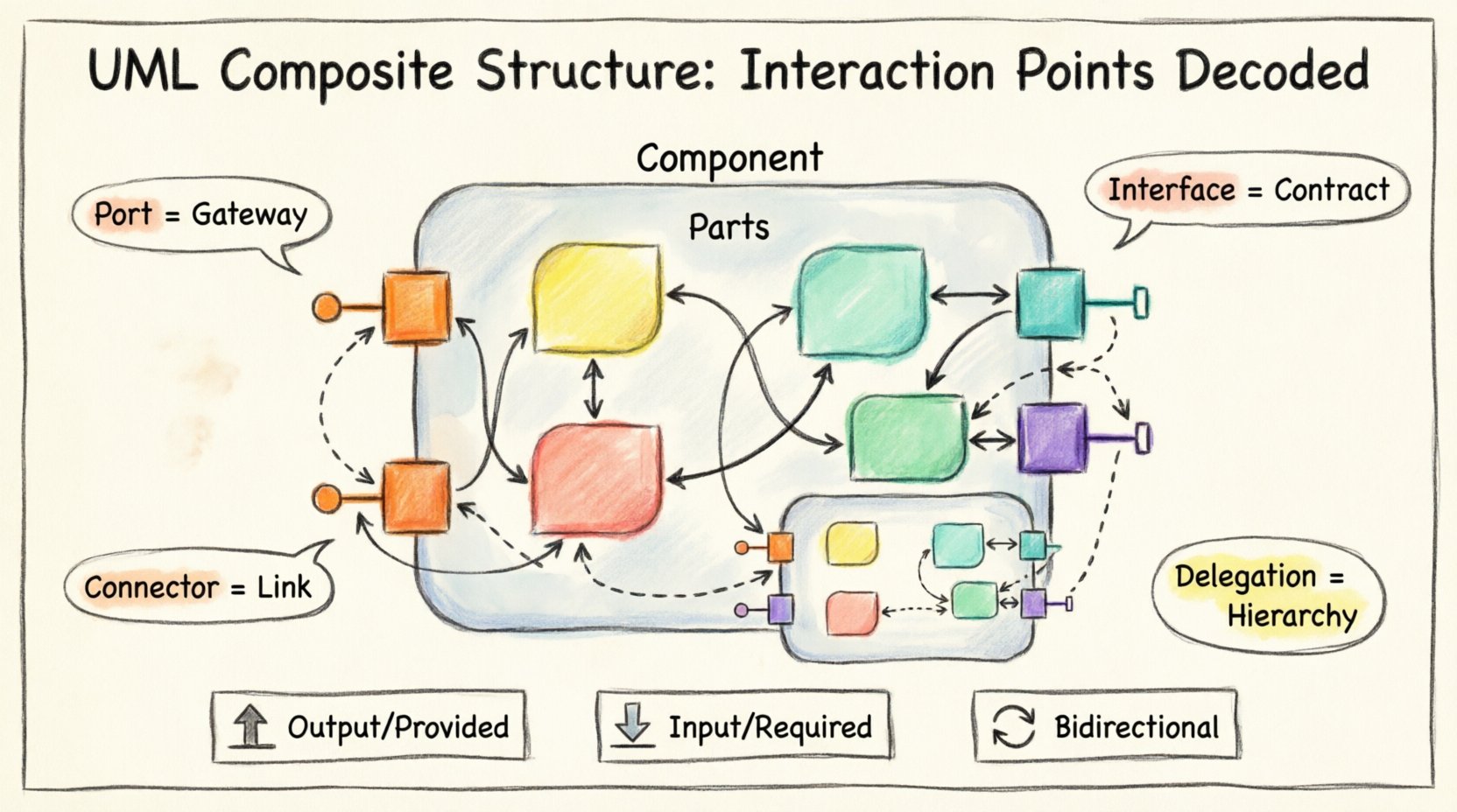
- Ports are Gateways: They control access to internal parts.
- Interfaces are Contracts: They define what is possible.
- Connectors are Links: They bind the parts together.
- Delegation is Hierarchy: It passes responsibility down the chain.
- Documentation is Vital: The diagram must match the reality.
Apply these principles to your next project. Start with the structure. Define the points. Draw the connections. Build with confidence.

