Software architecture relies heavily on visual representation to communicate complex systems. Among the Unified Modeling Language (UML) specifications, structural diagrams play a pivotal role in defining the static aspects of a system. One specific diagram type often overlooked yet highly powerful is the Composite Structure Diagram. This guide provides a detailed examination of the UML Composite Structure Diagram and compares it against other structural models available in the specification. 📋
Understanding the distinctions between these models is essential for architects and developers. Each diagram serves a unique purpose, highlighting different facets of the system design. By selecting the appropriate model, teams can ensure clarity, reduce ambiguity, and maintain a robust design throughout the development lifecycle. 🚀
Understanding the Composite Structure Diagram 🧩
The Composite Structure Diagram is designed to show the internal structure of a classifier. While standard class diagrams focus on attributes and operations at the class level, the Composite Structure Diagram dives deeper. It reveals the internal parts, roles, and interactions within a specific class or component. This level of detail is crucial for complex systems where internal composition dictates behavior. 🛠️
Key Components of the Diagram
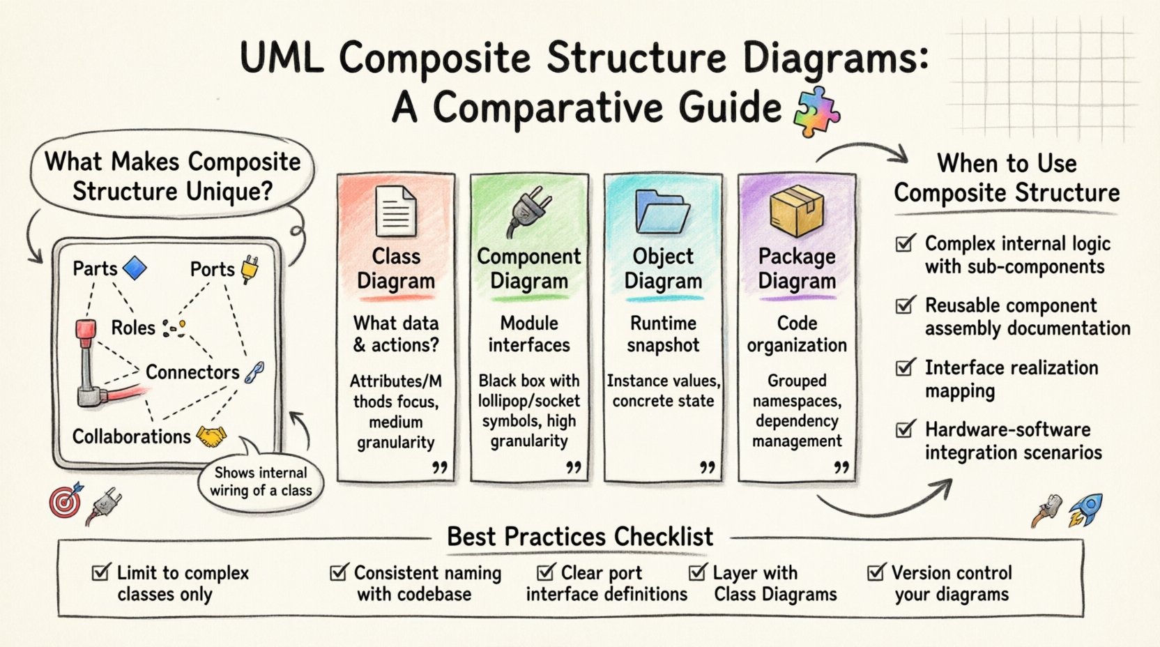
To utilize this model effectively, one must understand its core elements:
- Classifier: The class or component being analyzed. It acts as the container for the internal structure.
- Part: Represents the constituent objects or components that make up the classifier. Parts are the building blocks inside the whole.
- Role: Defines the interface or contract that a part fulfills within the composite structure. It specifies how the part interacts with the rest of the system.
- Port: A designated point of interaction on a classifier. Ports define the boundaries through which the classifier communicates with the external environment.
- Connector: Links parts together or connects parts to ports. These define the internal wiring and data flow.
- Collaboration: A named set of roles and connectors that defines a pattern of interaction between parts.
This granularity allows architects to model the internal wiring of a class without exposing the entire class interface. It separates the internal implementation details from the external contract. 🎯
Comparison with Class Diagrams 📄
The Class Diagram is the most widely used structural model in UML. It depicts the system’s static structure by showing classes, their attributes, operations, and relationships. However, the Class Diagram operates at a higher level of abstraction compared to the Composite Structure Diagram. 📊
Focus of Attention
- Class Diagram: Focuses on the data structure and the public API of the system. It answers the question: “What data exists and what actions can be performed?”
- Composite Structure Diagram: Focuses on the internal organization. It answers the question: “How is this class built from smaller pieces?”
Relationship Representation
- Class Diagram: Uses associations, aggregations, and compositions to link different classes together. These relationships are often external.
- Composite Structure Diagram: Uses internal connectors to link parts within the same classifier. It visualizes the aggregation of parts into a whole.
When designing a system, the Class Diagram provides the map of the territory, while the Composite Structure Diagram provides the blueprint of a specific building. Both are necessary for a complete picture, but they serve different stages of the design process. 🗺️
Comparison with Component Diagrams 🔌
Component Diagrams are another structural model that focuses on the physical or logical components of a system. They are often used to show the modular architecture and the dependencies between modules. ⚙️
Scope and Granularity
- Component Diagram: Operates at a higher level of granularity. It treats a class or a subsystem as a single black box component. It emphasizes interfaces and provided/required services.
- Composite Structure Diagram: Operates at a lower level. It opens the black box to show the internal parts. It emphasizes how the component is assembled internally.
Interface Handling
- Component Diagram: Uses lollipop and socket symbols to denote provided and required interfaces between components. The focus is on the boundary.
- Composite Structure Diagram: Uses Ports to denote interaction points. It can show how internal parts realize interfaces. The focus is on the boundary and the internal realization.
For system integrators, the Component Diagram is often sufficient. For developers implementing a specific complex class, the Composite Structure Diagram offers necessary detail. It bridges the gap between high-level architecture and low-level code implementation. 💻
Comparison with Object Diagrams 🗂️
Object Diagrams capture a snapshot of the system at a specific point in time. They show instances of classes and the links between them. While similar to Class Diagrams in appearance, they represent dynamic states rather than static types. ⏱️
Type vs Instance
- Object Diagram: Represents specific instances. It shows actual data values and relationships at runtime.
- Composite Structure Diagram: Represents the type definition. It shows the potential internal structure that any instance of that class could have.
Structural Focus
- Object Diagram: Often used for testing or debugging to verify runtime states.
- Composite Structure Diagram: Used during design to define the composition rules that instances must follow.
While Object Diagrams validate the system, Composite Structure Diagrams define the system. They are complementary tools in the architect’s toolkit. 🔧
Comparison with Package Diagrams 📦
Package Diagrams organize model elements into groups to manage complexity. They handle the high-level organization of the codebase, such as namespaces or modules. 🗂️
Organization vs Composition
- Package Diagram: Focuses on grouping. It helps manage dependencies between large modules of the system.
- Composite Structure Diagram: Focuses on composition. It helps manage dependencies between parts within a single class or component.
Package Diagrams prevent the model from becoming a tangled mess by enforcing boundaries between major sections. Composite Structure Diagrams prevent the model from becoming too abstract by enforcing boundaries within sections. 🧱
Comparative Analysis Table 📋
The following table summarizes the key differences between the Composite Structure Diagram and other common structural models. This overview aids in selecting the right tool for the specific design challenge. 📉
| Feature | Composite Structure Diagram | Class Diagram | Component Diagram | Object Diagram |
|---|---|---|---|---|
| Primary Focus | Internal composition of a classifier | Attributes and Operations | Interfaces and Dependencies | Runtime Instances |
| Granularity | Low (Internal Parts) | Medium (Class Level) | High (Module Level) | Low (Instance Level) |
| Key Element | Parts, Ports, Roles | Attributes, Methods | Interfaces, Components | Object Instances |
| Usage Context | Complex Class Design | General System Design | System Integration | Validation & Testing |
| Abstraction Level | Implementation Details | Logical Structure | Physical/Logical Structure | Concrete State |
When to Use Composite Structure Diagrams 🤔
Choosing the right diagram depends on the problem at hand. The Composite Structure Diagram is not a replacement for Class or Component diagrams, but a specialized tool for specific scenarios. Here are situations where it is most effective.
1. Complex Internal Logic
When a class contains significant internal logic that relies on the interaction of multiple sub-components, a standard Class Diagram becomes cluttered. The Composite Structure Diagram allows for a clean separation of this internal logic. It prevents the external interface from being obscured by internal complexity. 🧠
2. Reusable Components
If a class is composed of standard, reusable parts that need to be documented, the Composite Structure Diagram highlights these parts explicitly. It shows how the class assembles these parts to achieve its function. This is useful for library design or framework development. 🔄
3. Interface Realization
When a class implements multiple interfaces through different internal parts, the diagram clarifies which part realizes which interface. This aids in understanding the delegation pattern within the code. 🎭
4. Hardware-Software Integration
In embedded systems, a class might represent a hardware driver. The Composite Structure Diagram can model the internal mapping between software objects and hardware registers or ports. This bridges the gap between software architecture and hardware constraints. ⚡
Best Practices for Modeling 🛡️
Creating effective diagrams requires adherence to certain principles. Poor modeling can lead to confusion rather than clarity. Follow these guidelines to ensure your diagrams communicate effectively.
- Limit Complexity: Do not use the Composite Structure Diagram for every class. Reserve it for classes that have complex internal structures. Overuse leads to diagram fatigue. 🚫
- Consistent Naming: Ensure that parts and roles are named consistently with the codebase. This facilitates traceability during development and maintenance. 🏷️
- Interface Clarity: Clearly define the interfaces provided and required by ports. Ambiguity here leads to integration errors later. 🧩
- Layering: Use this diagram in conjunction with Class Diagrams. The Class Diagram defines the contract; the Composite Structure Diagram defines the implementation. 📚
- Version Control: Treat diagrams as code. Store them in version control systems to track changes in internal structure over time. 📝
Implementation Considerations 💻
Translating these diagrams into actual code requires careful planning. The design decisions made in the diagram must be reflected in the implementation. Here are considerations for the development phase.
1. Mapping Parts to Code
Each part in the diagram should ideally correspond to a class, interface, or module in the codebase. If a part is a simple data holder, it might be a private attribute. If it is a behavior handler, it should be a separate class. 🧱
2. Managing Dependencies
The connectors in the diagram represent dependencies. In code, these translate to imports, references, or dependency injection. Minimizing the number of connectors reduces coupling. 🔗
3. Port Implementation
Ports define interaction points. In object-oriented programming, these often map to public methods or interface implementations. Ensuring ports are well-defined prevents external code from relying on internal details. 🚪
4. Refactoring
As the system evolves, the internal structure may change. The diagram should be updated to reflect refactoring. If a part is removed or replaced, the diagram must be adjusted to avoid technical debt. 🔄
Common Pitfalls to Avoid ⚠️
Even experienced architects make mistakes when modeling internal structures. Being aware of common pitfalls helps in maintaining diagram quality.
- Over-Engineering: Creating detailed composite structures for simple classes adds unnecessary overhead. Simplicity should be prioritized. 📉
- Inconsistency: Having different internal structures for the same class in different diagrams causes confusion. Maintain a single source of truth. 🧭
- Ignoring Interfaces: Focusing only on parts and ignoring the roles they play leads to a disconnected design. The interface is the contract; the parts are the workers. 👷
- Static Thinking: While structural, these diagrams should imply dynamic behavior. Consider how parts interact at runtime, not just how they sit in memory. ⏳
The Role in System Lifecycle 🔄
The Composite Structure Diagram plays a role throughout the system lifecycle, not just during the initial design phase.
Design Phase
During design, it helps architects decide on the decomposition of complex classes. It forces the team to think about internal boundaries and responsibilities. 🎨
Development Phase
Developers use the diagram to understand how to implement a class. It serves as a reference for unit testing and integration. 👨💻
Maintenance Phase
When fixing bugs or adding features, the diagram helps identify which internal parts are affected. It reduces the risk of unintended side effects. 🛠️
Documentation Phase
For new team members, the diagram explains the internal workings of complex subsystems. It serves as a knowledge repository for the organization. 📖
Conclusion on Structural Modeling 🏁
Selecting the appropriate structural model is a critical decision in software architecture. The UML Composite Structure Diagram offers a unique perspective by focusing on internal composition. It complements Class, Component, and Object diagrams by providing a deeper view of specific classifiers. By understanding the strengths and limitations of each model, teams can create designs that are both robust and maintainable. 🌟
The choice of diagram should align with the complexity of the system and the needs of the stakeholders. For simple systems, standard Class Diagrams may suffice. For complex, component-heavy systems, the Composite Structure Diagram becomes indispensable. It ensures that internal logic is documented, understood, and managed effectively. 🏗️
Continued refinement of modeling skills leads to better software products. As systems grow in complexity, the need for precise structural documentation increases. The Composite Structure Diagram stands as a vital tool in this endeavor, providing clarity where other models fall short. 📈
By integrating these diagrams into standard workflows, organizations can reduce ambiguity and improve collaboration. The investment in detailed modeling pays off in reduced maintenance costs and faster development cycles. It is a practice that separates casual coding from professional engineering. 🛡️
Ultimately, the goal is clear communication. Whether through Class Diagrams or Composite Structure Diagrams, the aim remains the same: to convey the system design accurately to all participants. Mastery of these tools ensures that the design intent is preserved from concept to deployment. 🚀

