Software architecture is often a source of confusion. Teams struggle to communicate how systems work, new hires take months to onboard, and existing codebases become difficult to modify without breaking things. A common root cause is the lack of standardized documentation. Without a shared language for visualizing design, architects and developers end up speaking different dialects.
The C4 Model provides a structured approach to creating software architecture diagrams. It defines four levels of abstraction, each serving a specific audience and purpose. By focusing on the right level of detail, teams can improve communication, reduce technical debt, and maintain a clear understanding of their systems over time.
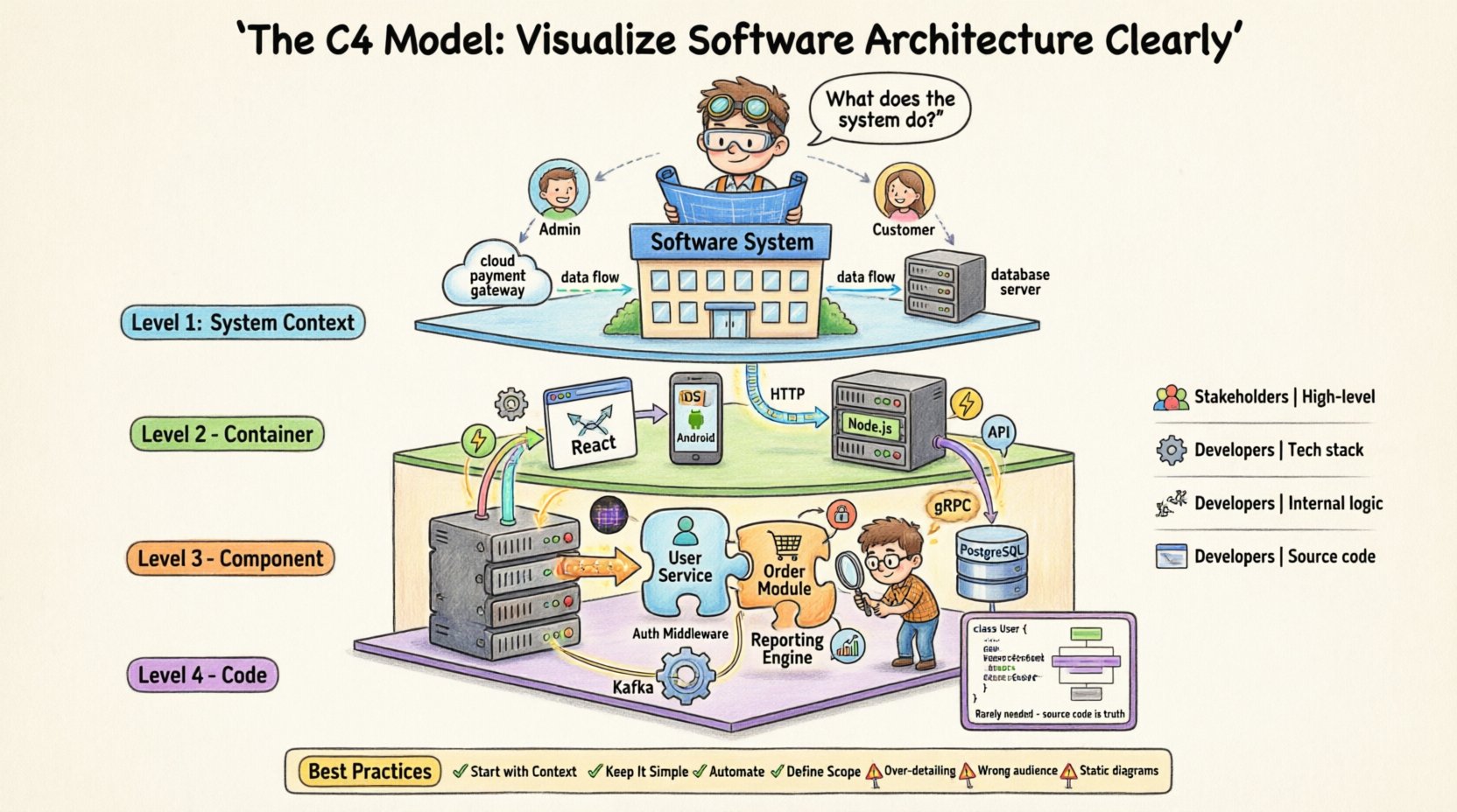
🧭 What Is the C4 Model?
The C4 Model is a hierarchical method for documenting software architecture. It organizes diagrams into four distinct levels, ranging from high-level context to low-level code structure. This hierarchy allows different stakeholders to view the system at the appropriate level of granularity.
Unlike rigid methodologies that dictate specific notation, the C4 Model focuses on the abstraction level. It answers the question: “What does this audience need to know right now?” This flexibility makes it adaptable to various project types, from microservices to monolithic applications.
Why Use a Hierarchical Approach?
- Reduces Cognitive Load: Stakeholders do not need to see every class or database table to understand the system.
- Improves Focus: Teams can concentrate on specific concerns, such as security boundaries or data flow, without getting lost in implementation details.
- Facilitates Maintenance: When the architecture changes, you know exactly which diagrams require updates.
- Standardizes Communication: Everyone understands what a “Container” or “Component” means in the context of the project.
🌍 Level 1: System Context Diagram
The System Context diagram provides the widest view of the software. It answers the question: “What does this system do, and who or what interacts with it?” This diagram is typically the first artifact created when starting a new project or documenting an existing one.
Key Elements
- The Software System: Represented as a single box in the center. This is the boundary of the application being documented.
- Users: People or roles who interact directly with the system (e.g., Administrators, Customers, Managers).
- External Systems: Other software applications that the system communicates with (e.g., Payment Gateways, Authentication Services, Legacy Databases).
- Relationships: Arrows connecting users and systems to the main box, indicating the direction of data flow.
Who Reads This?
- Project Stakeholders
- Business Analysts
- Non-Technical Team Members
- New Developers (for high-level onboarding)
This level avoids technical jargon. Instead of mentioning APIs or protocols, it focuses on business value and data exchange. For example, rather than drawing a REST endpoint, you simply draw a line from the “Customer Portal” to the “Payment Processor” labeled “Payment Data”.
📦 Level 2: Container Diagram
Once the boundaries are established, the Container diagram zooms in. It breaks the single system box into its constituent runtime environments. A container is a deployable unit that executes code. It represents a physical or logical boundary where software runs.
What Is a Container?
A container is not necessarily a Docker container. In this context, it refers to:
- A web application (e.g., React, Angular, Vue)
- A mobile application (e.g., iOS, Android)
- A server-side application (e.g., Java Spring Boot, Node.js, Python Django)
- A database (e.g., PostgreSQL, MongoDB, Redis)
- A file store or queue (e.g., S3, Kafka)
The goal is to understand the technology choices and how they communicate. Each container is a self-contained unit that performs a specific function within the larger system.
Key Elements
- Containers: Boxes representing the different runtime environments.
- Technologies: Labels indicating the technology stack (e.g., “Node.js”, “PostgreSQL”, “React”).
- Connections: Lines showing how containers talk to each other (HTTP, gRPC, TCP, Database Queries).
- External Systems: Links to the external systems identified in Level 1.
Why This Level Matters
This diagram is crucial for understanding deployment topology and security boundaries. It helps teams decide where to place load balancers, firewalls, and authentication mechanisms. It also highlights data ownership. For instance, if a web app talks directly to a database, that is a critical architectural decision to review.
⚙️ Level 3: Component Diagram
Level 3 dives deeper into a specific container. It answers the question: “How is this container built?” This diagram breaks down a container into its major internal components. Components are logical groupings of functionality within a container.
What Is a Component?
Components are the building blocks of the codebase. They are cohesive units that perform a specific responsibility. Examples include:
- A User Management Service
- An Order Processing Module
- A Reporting Engine
- An Authentication Middleware
The key characteristic of a component is that it exposes an interface. Other components interact with it through this interface, minimizing coupling.
Key Elements
- Components: Boxes inside the container boundary.
- Interfaces: Arrows showing how components communicate (APIs, function calls, events).
- Responsibilities: Brief descriptions of what each component does.
When to Use This Diagram
This level is primarily for developers. It helps during the design phase of a new feature or when refactoring an existing module. It clarifies dependencies. If Component A needs to change, you can see exactly which other components will be affected.
💻 Level 4: Code Diagram
Level 4 is the most detailed view. It maps directly to the source code. It shows classes, interfaces, and methods. In most scenarios, this level is not required for documentation purposes.
The source code is the single source of truth. Creating a diagram that mirrors the code often leads to rapid obsolescence. As the code changes, the diagram becomes outdated.
When to Use Level 4
- Complex Algorithms: When explaining a specific logic flow that is not obvious from the class names.
- Design Patterns: When demonstrating how a pattern is implemented (e.g., Strategy Pattern).
- Onboarding for Junior Devs: Occasionally helpful for understanding the internal structure of a specific class.
For general architecture documentation, it is usually better to rely on Level 3 and trust the developers to read the code for Level 4 details.
📊 Comparison of C4 Levels
The following table summarizes the differences between the four levels to help teams decide which diagrams to create.
| Level | Focus | Audience | Granularity |
|---|---|---|---|
| 1. System Context | Boundaries & External Systems | Stakeholders, Business | High (1 Box) |
| 2. Container | Runtime Environments & Tech Stack | Developers, Architects | Medium (Multiple Boxes) |
| 3. Component | Internal Logic & Interfaces | Developers | Low (Logical Modules) |
| 4. Code | Classes & Methods | Developers | Very Low (Source Code) |
🛠️ Best Practices for Implementation
Creating the diagrams is only half the battle. Maintaining them ensures they remain useful. Here are strategies for effective implementation.
1. Start with the System Context
Never begin with a component diagram. Establish the boundaries first. If you do not know what is inside the system, you cannot know what it interacts with. Start with Level 1, then expand to Level 2 only if necessary.
2. Keep It Simple
- One Diagram Per Page: Avoid cluttering a single view with too much information.
- Consistent Naming: Use the same names for components across all diagrams.
- Standard Notation: Stick to standard shapes and arrow types to ensure readability.
3. Automate Where Possible
Manual maintenance leads to stale documentation. If you have a tool that can generate diagrams from code annotations or configuration files, use it. This reduces the friction between code changes and documentation updates.
4. Define the Scope
Not every system needs all four levels. A simple internal tool might only require a System Context diagram. A complex microservice architecture might require all four levels for different services. Assess the complexity before committing to the effort.
🚫 Common Mistakes to Avoid
Even with a solid model, teams often fall into traps that reduce the value of the documentation.
Mistake 1: Over-Detailing Level 1
Adding too much detail to the System Context diagram defeats its purpose. Do not list every API endpoint. Keep the focus on external systems and users. If a stakeholder needs to know an endpoint exists, they can ask, or it can be documented in an API specification.
Mistake 2: Ignoring the Audience
Creating a Component diagram for a CEO is useless. They need to know about business value and data flow, not internal modules. Tailor the diagram to the reader’s needs. If you are writing for developers, focus on interfaces and data ownership.
Mistake 3: Treating Diagrams as Static
Documentation is not a one-time task. When the architecture changes, the diagrams must change. If the team treats diagrams as a checkbox exercise, they will become inaccurate within weeks. Integrate diagram updates into the definition of done for features.
Mistake 4: Using the Wrong Level
Using a Container diagram to explain business logic is confusing. Using a Component diagram to explain deployment topology is insufficient. Ensure you are using the correct abstraction level for the question you are trying to answer.
🔄 The Lifecycle of Architecture Documentation
Documentation should evolve alongside the software. This lifecycle approach ensures the diagrams remain relevant.
Phase 1: Discovery
During the initial planning phase, create the System Context diagram. Identify the main users and external dependencies. This sets the scope for the project.
Phase 2: Design
As the team begins designing the solution, create the Container diagram. Decide on the technology stack and how the parts connect. This is the time to make high-level architectural decisions.
Phase 3: Development
During development, create Component diagrams for complex modules. This helps developers understand the boundaries they need to respect. Update diagrams as features are completed.
Phase 4: Maintenance
As the system ages, review the diagrams during retrospectives. Are they still accurate? Do they help onboarding? If not, refactor the documentation as well as the code.
🤝 Communication and Collaboration
The C4 Model is not just about drawing boxes. It is about facilitating conversation.
- Workshops: Use the diagrams as a focal point for architecture review meetings.
- Whiteboarding: Start with a rough sketch to discuss ideas before formalizing them.
- Version Control: Store diagrams alongside code. This ensures they are reviewed during pull requests.
When everyone agrees on the visual representation, misunderstandings decrease. Decisions become clearer. The cost of rework drops because the requirements are better understood.
🎯 Conclusion
The C4 Model offers a pragmatic solution to the chaos of software architecture documentation. By providing four clear levels of abstraction, it allows teams to communicate effectively without getting bogged down in unnecessary detail.
It is not a silver bullet. It requires discipline to keep the diagrams up to date. However, the investment pays off in faster onboarding, clearer design decisions, and reduced technical debt. Whether you are building a new application or refactoring an old one, adopting this model can provide a clear path to understanding your system.
Focus on the right level for the right audience. Start simple. Iterate often. And remember that the goal is clarity, not perfection.

