Software architecture is the backbone of any robust digital system. It defines the structure, behavior, and interactions within a complex application. Without a clear visualization of these systems, teams often struggle with miscommunication, technical debt, and scaling challenges. The C4 Model provides a standardized approach to documenting software architecture at various levels of detail. It allows engineers, stakeholders, and developers to understand the system without getting lost in unnecessary complexity.
This guide explores the hierarchy of the C4 Model, explaining how to implement it effectively across your development lifecycle. We will cover the four distinct levels, the relationships between them, and how to maintain these diagrams as your system evolves. By the end, you will understand how to leverage this framework to improve clarity and collaboration within your organization.
🧩 Understanding the Hierarchy
The core strength of the C4 Model lies in its abstraction. It avoids the pitfalls of trying to draw everything at once. Instead, it breaks down the architecture into four specific levels. Each level serves a different audience and answers different questions. Moving from a high-level overview to granular details allows for better comprehension and targeted documentation.
Here is a breakdown of the four levels:
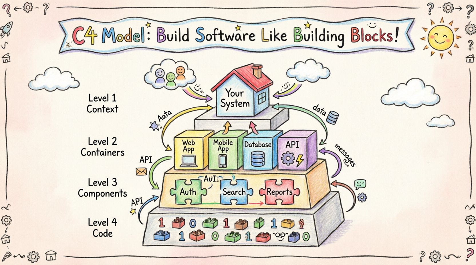
- Level 1: Context – The big picture view for everyone.
- Level 2: Container – The technology choices for architects and senior developers.
- Level 3: Component – The internal logic for developers and team members.
- Level 4: Code – The detailed implementation for specific engineers.
Not every project requires all four levels. Many teams find that Levels 1 through 3 provide sufficient clarity. Level 4 is often optional and reserved for complex algorithms or critical performance modules. The following table summarizes the key distinctions between these layers.
| Level | Focus | Primary Audience | Typical Duration |
|---|---|---|---|
| 1. Context | System boundary and external users | Stakeholders, Management, Product Owners | 1-2 hours |
| 2. Containers | Technology stack and data flows | Architects, DevOps, Senior Engineers | 1-3 days |
| 3. Components | Logical structure and responsibilities | Developers, Team Leads | 1-2 weeks |
| 4. Code | Classes and methods | Specialized Engineers | Variable |
🌍 Level 1: System Context Diagram
The Context diagram is the entry point for understanding any system. It defines the boundaries of your application and how it interacts with the outside world. This level is crucial because it sets the stage for all subsequent documentation. It answers the question: “What does this system do, and who uses it?”
When creating a Context diagram, you should focus on the following elements:
- People: Users interacting with the system. These could be end-users, administrators, or external services.
- Software Systems: Other systems that your application communicates with. For example, a payment gateway or an email service.
- Relationships: The data flows between the system and the external entities.
Keep this diagram simple. It should fit on a single page. Avoid technical jargon here. The goal is to communicate value and scope, not implementation details. If a stakeholder cannot understand the Context diagram within five minutes, it needs simplification.
Key Elements to Include
- The central system box representing your application.
- External systems connected via data flow arrows.
- Labels describing the type of data being exchanged (e.g., “User Data”, “Payment Info”).
- Clear distinction between actors (people) and systems (machines).
📦 Level 2: Container Diagram
Once the boundary is established, the Container diagram dives deeper into the technology stack. A container is a distinct, deployable unit of software. Examples include a web application, a mobile app, a microservice, or a database. This level is essential for understanding the physical or logical separation of your architecture.
This diagram answers the question: “How is the system built, and what technologies are used?” It bridges the gap between business requirements and technical implementation.
When drafting a Container diagram, consider these aspects:
- Technologies: Specify the language, framework, or database technology (e.g., Node.js, PostgreSQL, React).
- Responsibilities: Each container should have a single, clear purpose. Avoid putting multiple responsibilities into one box.
- Connections: Show how containers talk to each other. Are they using HTTP, gRPC, or a message queue?
Best Practices for Containers
- Do not show individual servers or instances unless they represent a specific logical role.
- Group containers by their function (e.g., “Frontend”, “Backend”, “Infrastructure”).
- Ensure the data flow arrows are labeled with the protocol used.
- Exclude code-level details. This is about the unit of deployment, not the classes inside.
This level is often where architectural decisions are made. It defines the boundaries between services and the protocols used for communication. A well-documented Container diagram helps DevOps teams understand deployment requirements and helps developers understand integration points.
🔧 Level 3: Component Diagram
Inside a container, the Component diagram reveals the logical structure. A component is a distinct part of a container that performs a specific function. For example, a web application might contain components for “User Authentication”, “Search Functionality”, and “Report Generation”.
This level is targeted at developers who need to understand the internal logic without reading every line of code. It answers the question: “How is this container organized internally?”
Key characteristics of a Component diagram include:
- Logical Boundaries: Components represent logical groupings, not necessarily physical files.
- Interfaces: Show how components interact with each other. This often involves public methods or API endpoints.
- Dependencies: Highlight which components rely on others to function.
The Component diagram is the most detailed level that should be actively maintained for most projects. It serves as the blueprint for new feature development and helps onboard new team members. It reduces the risk of accidental tight coupling between different parts of the system.
Structuring Components Effectively
- Use naming conventions that reflect the business domain.
- Keep the number of components per container manageable (ideally under 20).
- Use colors or shapes to indicate different types of components (e.g., API, Database, Cache).
- Document the input and output data for each component.
💻 Level 4: Code Diagram
Level 4 focuses on the actual code implementation. It shows classes, methods, and data structures. This level is rarely drawn manually. Instead, it is often generated from the codebase itself.
While valuable for specific cases, maintaining Level 4 diagrams manually is often unsustainable. Most teams skip this level unless they are dealing with highly complex algorithms or legacy code migration. If you choose to use this level, consider automated tools that generate the diagrams directly from source code repositories.
🔗 Relationships and Data Flows
Across all levels, the relationships between elements are just as important as the elements themselves. A diagram without context on how things connect is merely a map of islands. Properly labeled relationships ensure that the flow of information is clear.
Types of Relationships
- Uses: One component depends on another for functionality.
- Sends Data To: Information flows from one entity to another.
- Reads Data From: One entity retrieves information from another.
- Controls: One system manages the lifecycle of another.
Labeling these relationships is critical. A line connecting two boxes is ambiguous. Adding a label like “REST API” or “Async Message” provides necessary context. This distinction helps teams understand latency requirements and error handling strategies.
🛠️ Implementation Strategy
Adopting the C4 Model requires a shift in documentation culture. It is not just about drawing pictures; it is about maintaining a living source of truth. Here is a strategy for integrating this model into your workflow.
1. Start with the Context
Before writing code or choosing technologies, define the Context. Gather stakeholders and agree on the boundaries. This prevents scope creep later. If the Context diagram is not agreed upon, the rest of the architecture will likely drift.
2. Iterate Through Levels
Do not try to create all levels at once. Start with Level 1. Once that is stable, move to Level 2. As features are built, flesh out Level 3. This incremental approach prevents documentation fatigue.
3. Keep It Up to Date
Outdated diagrams are worse than no diagrams. They create false confidence and mislead developers. Establish a rule where code changes trigger diagram updates. If a new container is added, the diagram must reflect that change immediately.
4. Integrate with Code
Where possible, link diagrams to the actual code. Annotations in the code should reference the component names in the diagram. This creates a feedback loop between design and implementation.
📊 Common Pitfalls to Avoid
Even with a solid framework, teams often stumble during implementation. Understanding these common mistakes can save time and effort.
- Over-Engineering: Trying to document every single class in the system. Stick to Level 3 for most cases.
- Ignoring the Audience: Drawing a Component diagram for a CEO. Match the level of detail to the reader’s needs.
- Static Diagrams: Treating the diagram as a one-time task. Architecture evolves, and so must the documentation.
- Too Many Dependencies: Creating a web of connections that makes the diagram unreadable. Use abstraction to simplify complex relationships.
- Tool Overload: Focusing too much on the drawing tool rather than the content. The tool is secondary to the clarity of the message.
🔄 Maintenance and Lifecycle
Maintaining architecture documentation is a continuous process. It requires discipline and integration into the development pipeline. Here are strategies to keep your C4 documentation healthy.
Version Control
Store your diagrams in the same repository as your code. This ensures that diagram versions align with code releases. Use commit messages to explain why a diagram changed. This provides an audit trail for architectural decisions.
Automated Checks
Use scripts to verify that the diagrams match the code. If a new microservice is deployed but not reflected in the diagram, the build should fail or generate a warning. This enforces discipline without manual oversight.
Regular Reviews
Schedule architectural reviews where the team walks through the diagrams together. This is an excellent opportunity to identify technical debt or inconsistencies. It also serves as a knowledge transfer session for new hires.
🤝 Collaboration and Communication
The C4 Model is fundamentally a communication tool. It bridges the gap between technical and non-technical stakeholders. By standardizing the way we talk about software, we reduce ambiguity.
For Developers
Developers use the diagrams to understand where their code fits in the larger ecosystem. It helps in debugging and feature planning. When a bug occurs, the diagram shows where the data flow breaks.
For Management
Management uses the Context diagram to understand the business value. They can see how the system interacts with customers and partners. This aids in budgeting and strategic planning.
For New Hires
Onboarding is significantly faster with clear documentation. A new developer can look at the Container diagram to understand the stack and the Component diagram to understand the code structure. This reduces the time-to-productivity.
📈 Scaling the Documentation
As systems grow, so does the complexity of the documentation. It is common for a single diagram to become too crowded as the system scales. In these cases, you should split the documentation into multiple views.
For example, instead of one massive Container diagram, create separate diagrams for “User Facing Services”, “Internal Services”, and “Data Services”. This keeps the information digestible. The C4 Model supports this approach through its flexible hierarchy.
🧭 Final Thoughts
Implementing the C4 Model is an investment in the long-term health of your software. It requires an upfront effort to create and maintain the diagrams, but the return on investment is significant. Teams that adopt this model report fewer misunderstandings, faster onboarding, and more resilient systems.
Remember that the goal is clarity, not perfection. A simple, accurate diagram is better than a complex, detailed one that no one reads. Start small, focus on the levels that matter most to your team, and evolve the documentation as your system grows. By adhering to these principles, you build a foundation that supports innovation and stability.
Software architecture is not just about code; it is about communication. The C4 Model provides the vocabulary and structure needed to speak clearly about complex systems. Embrace it as a tool for collaboration, and watch your team’s efficiency and product quality improve.

