Software architecture is more than just drawing boxes and arrows. It is about communication, clarity, and creating a shared vision for the team. The C4 model provides a structured approach to documenting software architecture at different levels of abstraction. This guide explores the layers of the C4 model, how to apply them, and why they matter for modern development teams. 🚀
Understanding the Need for Architecture Documentation 📝
When building complex systems, assumptions can lead to significant technical debt. Developers often struggle to understand how different parts of a system interact. Without clear documentation, onboarding new team members becomes slow and error-prone. Architecture diagrams serve as a single source of truth, bridging the gap between high-level business goals and low-level implementation details.
Many teams fail because they document too little or too much. Too little leaves ambiguity. Too much creates maintenance nightmares. The C4 model solves this by defining four specific levels of detail. Each level targets a specific audience and answers specific questions. This hierarchy ensures that the right information reaches the right people at the right time.
- Clarity: Reduces ambiguity in system interactions.
- Maintenance: Helps identify dependencies before they cause issues.
- Onboarding: Accelerates the time it takes for new developers to contribute.
- Communication: Provides a common language for technical and non-technical stakeholders.
Level 1: System Context Diagram 🌍
The System Context diagram is the highest level view. It describes the software system as a single black box and shows its relationships with the users and other systems that interact with it. This diagram answers the question: What does this system do, and who or what uses it?
Key Elements
- Software System: Represented as a central box. This is the main subject of the documentation.
- People: Users or roles who interact with the system. Examples include administrators, customers, or external partners.
- Other Systems: External services or applications that communicate with the system. This includes APIs, databases, or third-party integrations.
- Relationships: Arrows indicating the flow of data or requests between the system and its surroundings.
This level is ideal for stakeholders who need a high-level overview. It does not show internal details. It focuses on boundaries and external interactions. When creating this diagram, keep the number of relationships manageable. If the list grows too long, consider splitting the system into smaller subsystems.
Level 2: Container Diagram 📦
Once the context is established, we zoom in to the Container level. A container is a runtime environment that holds code and data. Examples include web applications, mobile apps, microservices, or databases. This diagram shows how the system is built and deployed.
Defining Containers
Containers are distinct from components because they represent a deployable unit. They are the building blocks of the architecture. This level answers the question: How is the system built, and what technologies are used?
- Web Applications: Front-end interfaces running in a browser.
- Mobile Applications: Native or hybrid apps running on devices.
- Microservices: Independent services running in containers or servers.
- Database: Storage systems for persistent data.
- Batch Jobs: Scheduled processes for data processing.
Interactions
At this level, you must define how containers talk to each other. Use standard protocols like HTTP, TCP, or messaging queues. Label the relationships to indicate the direction of data flow. For example, a web application might send requests to a microservice, which then reads from a database.
Include technology tags to specify the stack. For instance, label a container as “Java Spring Boot” or “React”. This helps developers understand the technical requirements without reading the code. It also aids in planning for infrastructure and security constraints.
Level 3: Component Diagram 🔧
Inside a container, the Component diagram reveals the internal structure. A component is a logical unit of code within a container. It groups related functionality together. This level answers the question: How does the code work internally?
Components vs. Classes
Do not confuse components with individual classes or functions. A component represents a cohesive module. For example, in a banking application, a “Transaction Processing” component might exist within the “Account Service” container. This component handles the logic for moving money but does not define the specific database queries.
- Responsibility: Each component should have a clear purpose.
- Dependencies: Show how components interact with one another.
- Interfaces: Define the public methods or APIs exposed by the component.
This level is most useful for developers working on the codebase. It helps them understand where to place new features. It also highlights coupling between different parts of the system. If two components rely heavily on each other, consider refactoring to reduce complexity.
Level 4: Code Diagram 💻
The fourth level is the Code diagram. It shows the structure of the code itself, including classes, interfaces, and methods. In most cases, this level is generated automatically from the source code. It is rarely hand-maintained because it changes frequently with every commit.
When to Use
Use this level only when deep understanding of the implementation is required. For most architectural discussions, the Component level is sufficient. Code diagrams can become overwhelming if not filtered. They are best used for specific debugging sessions or detailed design reviews.
Automate the generation of these diagrams. Tools can extract the structure from the codebase and update the documentation. This ensures the diagrams remain accurate without adding manual maintenance overhead.
Visualizing the Hierarchy 📊
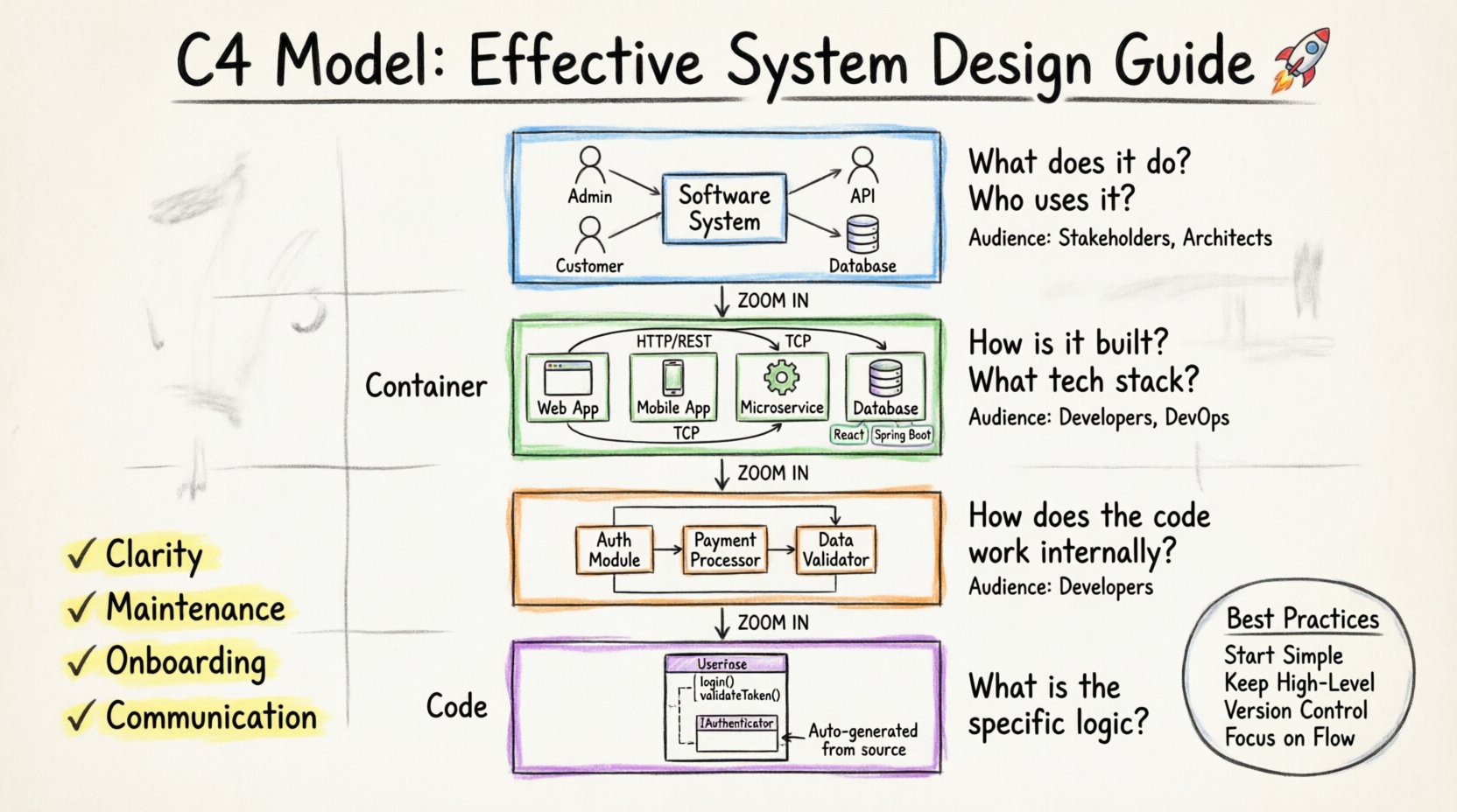
Understanding the relationship between these levels is crucial. Each level zooms in on the previous one. The System Context shows the world. The Container shows the building blocks. The Component shows the internal logic. The Code shows the implementation.
| Level | Focus | Audience | Typical Questions |
|---|---|---|---|
| System Context | Boundaries & External Systems | Stakeholders, Architects | What is the system? Who uses it? |
| Container | Technologies & Deployable Units | Developers, DevOps | How is it built? What tech stack? |
| Component | Internal Structure | Developers | How does the code work? |
| Code | Classes & Methods | Developers | What is the specific logic? |
Best Practices for Documentation ✍️
Creating diagrams is one thing. Keeping them useful is another. Documentation that is outdated is worse than no documentation at all. Follow these practices to maintain value.
- Start Simple: Begin with the System Context. Do not jump to the Component level immediately. Establish the boundaries first.
- Keep it High-Level: Avoid clutter. If a diagram has more than 20 elements, it may be too detailed. Break it down into smaller diagrams.
- Use Metadata: Add descriptions to every element. Explain what a container or component does in a sentence or two.
- Version Control: Store diagrams alongside the code. This ensures they are updated when the code changes.
- Focus on Flow: Emphasize how data moves. Static structure is important, but dynamic flow explains behavior better.
Common Pitfalls to Avoid ⚠️
Teams often make mistakes when applying this model. Recognizing these errors early can save significant time.
- Over-Engineering: Trying to document every single class. Focus on the logical structure, not the implementation details.
- Ignoring Updates: Creating a diagram once and never touching it again. Treat diagrams as living documents.
- Tool Dependency: Relying too heavily on specific tools. The value is in the model, not the drawing software. Ensure the output is accessible.
- Mixing Levels: Putting component details inside a context diagram. Keep the levels distinct to maintain clarity.
- Static Relationships: Showing connections that are not active. Only document actual data flows and dependencies.
Integrating into the Workflow 🔄
Documentation should not be a separate task. It should be part of the development process. Integrate diagram creation into the pull request workflow. When a new feature is added, the relevant diagram should be updated.
Review Process
Include architecture diagrams in code reviews. This ensures that the design matches the implementation. It also catches potential issues before they reach production. Reviewers can check if the new code fits the existing architecture.
Onboarding New Hires
Use the System Context and Container diagrams as the first reading material for new team members. This gives them a map of the system before they start writing code. It reduces the questions they need to ask and speeds up their contribution.
Technical Decision Making
When discussing technology choices, refer to the Container level. This helps visualize the impact of a decision. For example, moving from a monolith to microservices will change the Container diagram significantly. This visual aid supports better decision-making.
Tools and Technologies 🛠️
There are many tools available to create these diagrams. The choice depends on the team’s needs and preferences. Some tools support code generation, while others focus on manual drawing.
- Manual Drawing: Vector graphics editors allow for complete control. They are useful for one-off diagrams but hard to maintain at scale.
- Code-Based: Tools that generate diagrams from code ensure accuracy. They reduce the maintenance burden significantly.
- Cloud Platforms: Online collaboration tools allow teams to work together in real-time. This is useful for distributed teams.
Regardless of the tool, ensure the output format is portable. PDF or SVG formats allow sharing with stakeholders who do not have access to the editing tool. Avoid proprietary formats that lock you into a single platform.
Scaling the Model 📈
As systems grow, the number of diagrams can increase. A large organization might have dozens of systems, each with its own set of diagrams. Managing this requires a strategy.
Indexing
Create a central index or landing page. Link all diagrams together logically. This helps users navigate the documentation. Search functionality can also help locate specific components or containers quickly.
Abstraction
Use the System Context level to link multiple sub-systems. If a system is composed of several services, document them separately but link them in the context diagram. This maintains the hierarchy without overwhelming the viewer.
Automation
For large systems, automation is key. Script the generation of diagrams from the codebase. Schedule regular updates to ensure the documentation stays fresh. This reduces the risk of stale information.
The Impact on Team Culture 🤝
Documentation affects how a team works. A shared understanding of the architecture fosters collaboration. When everyone knows the boundaries, they can work independently without stepping on each other’s toes.
- Reduced Silos: Clear documentation breaks down barriers between teams.
- Knowledge Sharing: New members can learn faster without constant mentorship.
- Confidence: Developers feel more confident making changes when they understand the system.
- Quality: Better design leads to fewer bugs and easier maintenance.
Investing time in the C4 model pays dividends over the lifecycle of the software. It transforms architecture from a theoretical concept into a practical tool for daily work. By following these guidelines, teams can create documentation that is valuable, accurate, and sustainable. 🌟

