Software architecture is often the invisible backbone of any successful digital product. It defines how systems interact, how data flows, and how components are organized. Yet, communicating this complexity to stakeholders remains a persistent challenge. Too often, diagrams are either too high-level to be useful or too detailed to be understood. The C4 Model offers a structured approach to visualizing software architecture at multiple levels of abstraction. This guide explores the core principles of the C4 Model, providing a framework for architects to document systems clearly and effectively.
🧩 The Challenge of Architectural Communication
When building complex systems, the gap between design and implementation can widen if communication falters. Stakeholders range from business owners who need to understand high-level capabilities to developers who need to know how code is structured. A single diagram rarely satisfies everyone. Without a standardized notation, teams often create inconsistent documentation that becomes outdated quickly.
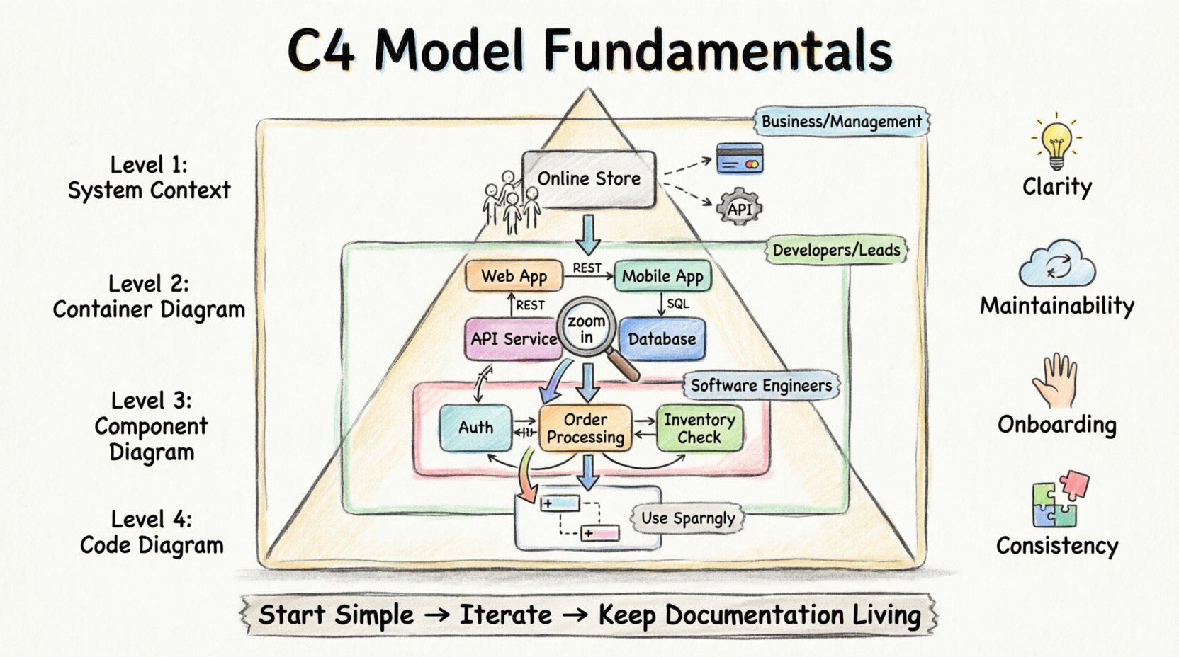
The C4 Model addresses this by introducing a hierarchy of diagrams. Each level serves a specific audience and answers a specific question. This hierarchy allows architects to zoom in and out of the system design without losing context. It ensures that the documentation remains relevant regardless of the technical depth required.
- Clarity: Reduces ambiguity in system design.
- Maintainability: Makes documentation easier to update.
- Onboarding: Helps new team members understand the system quickly.
- Consistency: Provides a common language for the team.
🌍 Level 1: System Context Diagram
The first level of the C4 Model is the System Context Diagram. This view represents the system as a single box and illustrates its relationship with the outside world. It is the highest level of abstraction and is typically the starting point for any architectural discussion.
👥 Who Needs This View?
This diagram is designed for non-technical stakeholders, including product managers, business analysts, and clients. It answers the question: “What does this system do, and who uses it?”
🔍 Key Elements
- The System: Represented as a central box. This is the boundary of your current project.
- Users: People or roles that interact with the system. These can be internal staff or external customers.
- External Systems: Other software applications that communicate with the system. These could be payment gateways, third-party APIs, or legacy databases.
- Relationships: Lines connecting the system to users and external systems. These indicate the flow of data or interaction.
In a typical e-commerce scenario, the system box might be labeled “Online Store.” Arrows would point from “Customer” to “Online Store,” and from “Payment Processor” to “Online Store.” This simple visualization establishes the scope of the project immediately.
📦 Level 2: Container Diagram
3Once the scope is defined, the next step is to look inside the system. The Container Diagram breaks the system down into its major building blocks. In this context, a “container” refers to a deployable unit of software. It is not a code-level container, but a runtime environment that holds the application logic.
🛠️ Defining Containers
A container can take many forms, such as a web application, a mobile application, a microservice, a database, or a file store. Each container represents a distinct boundary where code is deployed and executed.
- Web Applications: Browser-based interfaces.
- Mobile Applications: iOS or Android apps.
- API Services: Backend services exposing endpoints.
- Databases: Persistent storage layers.
- File Stores: Storage for documents or media.
🔄 Interactions Between Containers
The diagram focuses on how these containers communicate with each other. It highlights the protocols and data flows. For instance, a web application might talk to a database via SQL, or a mobile app might talk to an API via REST. Understanding these connections is vital for security and performance planning.
👥 Who Needs This View?
This level is primarily for developers and technical leads. It helps them understand the technology stack and the deployment topology without getting bogged down in code logic. It answers: “What technologies are used, and how are they connected?”
🔧 Level 3: Component Diagram
Inside each container, there is a logical structure. The Component Diagram dives into one specific container to show its internal organization. A component is a logical grouping of functionality. It is not a physical file, but a collection of code that performs a specific task.
🧱 Understanding Components
Components are cohesive units of functionality. They are designed to be independent and interchangeable. A component might handle user authentication, process payments, or generate reports. The goal is to show how the container achieves its purpose.
- Responsibility: Each component has a clear purpose.
- Interfaces: Components expose methods or APIs to interact with others.
- Dependencies: Components rely on other components within the same container.
📊 Visualizing Logic
While the Container Diagram shows the tech stack, the Component Diagram shows the logic. It helps developers see how data flows through the application. For example, a “Order Processing” component might call a “Inventory Check” component. This visibility aids in refactoring and identifying technical debt.
👥 Who Needs This View?
This is the primary diagram for software engineers. It serves as a blueprint for implementation. It answers: “How is the code organized inside this specific service?”
💻 Level 4: Code Diagram
The fourth level is the most detailed. It represents the structure of the code itself, similar to a class diagram in object-oriented programming. While the C4 Model emphasizes the first three levels, the Code level is useful for specific cases where deep technical understanding is required.
⚠️ When to Use Level 4
Code diagrams are often considered too verbose for general architectural discussions. They can become outdated the moment code is refactored. However, they are valuable for:
- Onboarding new developers to complex algorithms.
- Explaining intricate data structures.
- Documenting critical security logic.
Most teams find that maintaining Level 4 diagrams is too expensive. The recommendation is to use them sparingly, perhaps only for critical modules within a component.
📊 Comparing the Levels
Understanding the distinction between levels is crucial. Each level serves a different purpose and audience. The following table summarizes the differences.
| Level | Name | Audience | Question Answered |
|---|---|---|---|
| 1 | System Context | Business, Management | What does the system do? |
| 2 | Container | Developers, Leads | How is it built? |
| 3 | Component | Developers | How does it work? |
| 4 | Code | Developers (Deep Dive) | How is the code structured? |
🚀 Implementation Strategies
Adopting the C4 Model requires discipline. It is not enough to create diagrams once; they must be part of the workflow. Here are strategies to integrate the model effectively.
- Start Small: Begin with the System Context. Do not try to diagram everything at once. Establish the boundary first.
- Iterative Refinement: As the system grows, add Container and Component diagrams. Do not force all levels immediately.
- Living Documentation: Treat diagrams as code. Store them in the version control system alongside the source code. This ensures they are reviewed and updated during pull requests.
- Tooling: Use tools that support the C4 Model syntax. Many diagramming tools allow you to define relationships and generate views automatically.
⚠️ Common Pitfalls
Even with a clear model, teams can stumble. Being aware of common mistakes helps avoid wasted effort.
🔍 Over-Engineering
Creating a detailed Component diagram for a simple system is unnecessary. If the system is small, a single diagram might suffice. Match the level of detail to the complexity of the project.
🔄 Stale Diagrams
The biggest risk is documentation that does not match reality. If code changes but diagrams do not, trust in the documentation is lost. Automate updates where possible, or make diagram updates a mandatory part of the definition of done.
🧩 Mixing Levels
Do not mix abstraction levels in a single diagram. A System Context diagram should not show internal components. Keep the boundaries clear to maintain the value of the hierarchy.
🤝 Collaboration and Communication
The C4 Model is more than just drawing boxes; it is a communication tool. It aligns technical and non-technical teams. When everyone speaks the same language, requirements are clearer, and design flaws are caught earlier.
🗣️ During Planning
Use the System Context diagram to agree on scope. Ensure all stakeholders understand what is included in the project and what is external.
🛠️ During Development
Use the Container and Component diagrams to discuss implementation details. These diagrams help developers understand dependencies and avoid coupling.
🛡️ During Maintenance
When investigating issues, diagrams provide a map. Instead of reading through code, look at the flow of data. This speeds up debugging and reduces the time to resolution.
🔗 Relationships and Transitions
The power of the C4 Model lies in the connections between levels. Each level provides a different perspective on the same system. Moving from Level 1 to Level 2 is like zooming in on a map. You lose the view of the surrounding country, but you gain the detail of the roads.
Transitioning between levels requires care. When moving from Container to Component, ensure that the relationships remain consistent. If a database is connected to a web app in Level 2, the specific tables or queries inside the database should reflect that connection in Level 3.
Consistency is key. If the context diagram shows a user, the container diagram should show how that user authenticates. If the container diagram shows a service, the component diagram should show the logic that service contains. This continuity ensures the documentation remains a reliable source of truth.
📝 Best Practices for Diagramming
To get the most out of the model, follow these guidelines.
- Keep it Simple: Avoid clutter. If a diagram is too crowded, it is too complex. Break it down into multiple diagrams if needed.
- Use Standard Shapes: Stick to the C4 shapes. Boxes for systems, rounded rectangles for containers, and cylinders for databases. Consistency aids recognition.
- Label Clearly: Use clear labels for arrows. Explain the data flow. “User Login” is better than “Data Flow 1”.
- Review Regularly: Schedule reviews of the architecture diagrams. Ensure they still match the system state.
🌟 Conclusion
The C4 Model provides a robust framework for software architecture documentation. By separating concerns into distinct levels of abstraction, it allows teams to communicate effectively across different technical depths. It prevents the common pitfalls of overly detailed or overly vague diagrams. When implemented correctly, it becomes a living asset that supports development, maintenance, and onboarding. Architects who adopt this model gain a clearer vision of their systems and facilitate better collaboration across the organization.
Start with the System Context, refine with Containers and Components, and reserve Code diagrams for when they are truly needed. This disciplined approach ensures that architecture documentation remains valuable, accurate, and useful for everyone involved in the project.
