Software architecture is often the most misunderstood part of development. Teams struggle to align on how systems are built, how data flows, and where responsibility lies. Verbal descriptions are prone to misinterpretation, and dense documentation often becomes outdated quickly. To bridge this gap, the C4 model offers a structured approach to visualizing software architecture. It breaks down complexity into manageable layers, ensuring that everyone from stakeholders to developers understands the system design.
This guide explores the fundamental building blocks of the C4 model. By adopting these standardized diagrams, teams can improve clarity, reduce technical debt, and streamline the onboarding process for new members. We will examine each level of abstraction, discuss best practices for maintenance, and explain how these visual tools support long-term system health.
Understanding the C4 Model 🧩
The C4 model is a hierarchical approach to creating architecture diagrams. It was designed to address the “zoom level” problem common in technical documentation. A single diagram often tries to show too much or too little detail. The C4 model solves this by providing four distinct levels of abstraction. Each level serves a specific audience and answers a specific set of questions.
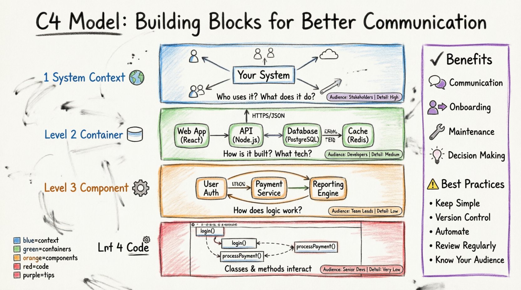
- Context: What does the system do? Who uses it?
- Containers: How is the system built? What technology is used?
- Components: How does the logic work inside a container?
- Code: How do the classes and functions interact?
By separating these concerns, you avoid overwhelming the reader. A stakeholder does not need to see database schemas to understand the system boundary. Conversely, a developer needs to see component interactions to implement features effectively. This separation of concerns creates a shared language across the organization.
Level 1: System Context Diagram 🌍
The System Context diagram is the starting point. It provides a high-level overview of the software system in question. Think of this as the “zoomed out” view. It defines the boundary of the system and shows how it interacts with the outside world.
Key Elements of a Context Diagram
- The System: A box representing the software you are designing. It should have a clear name and description.
- Users (Actors): People or roles who interact with the system. This includes end-users, administrators, and support staff.
- External Systems: Third-party services or legacy systems that the software communicates with. Examples include payment gateways, email services, or identity providers.
- Relationships: Lines connecting the actors and systems to the main box. These lines represent data flow or interactions.
When creating a Context diagram, keep the focus on business value. Avoid technical jargon. The goal is to answer: “What is this system, and why does it exist?” This diagram is particularly useful during the initial planning phase or when introducing a new project to non-technical stakeholders.
What to Include
- ✅ Clear system boundaries
- ✅ Distinct user roles
- ✅ High-level data flow
- ✅ External dependencies
What to Exclude
- ❌ Internal logic or processing steps
- ❌ Database schemas
- ❌ API endpoints or specific protocols
- ❌ Detailed error handling
Level 2: Container Diagram 📦
Once the boundary is established, the Container diagram zooms in. A container is a high-level runtime environment where the system runs. This could be a web application, a mobile app, a database, or a microservice.
The Role of Containers
Containers represent the physical or logical deployment units. They define the technology stack used at a macro level. For example, a container might be a “Node.js web application” or a “PostgreSQL database.” This level is crucial for understanding the infrastructure and deployment strategy.
When drawing this diagram, you should see how the containers connect to each other. If the system has a frontend and a backend, show the connection between them. If it uses an external cache, show that link. This helps developers understand the runtime topology.
Key Components to Document
- Technology Stack: Specify the language or platform (e.g., Python, Java, SQL).
- Responsibility: Briefly describe what each container does (e.g., “Handles user authentication,” “Stores transaction logs”).
- Connections: Show how data moves between containers using arrows. Label the arrows with the protocol or data type (e.g., “HTTPS,” “JSON”).
This diagram is often the most referenced by new developers. It provides the roadmap for setting up the development environment and understanding the deployment pipeline.
Level 3: Component Diagram ⚙️
The Component diagram zooms in further. It breaks down a single container into its internal parts. A component represents a logical grouping of functionality within a container. Unlike a container, a component does not have a runtime environment of its own; it lives inside the container.
Why Components Matter
At this level, you move from infrastructure to logic. Components represent features or modules. For a web application, a component might be “User Management,” “Payment Processing,” or “Reporting Engine.” This level helps developers who are working on specific features to understand where their code fits.
Components interact with each other through interfaces. You should show how data flows between these internal parts. This helps in identifying coupling and cohesion. If two components are tightly coupled, it might indicate a design issue.
Best Practices for Components
- Logical Grouping: Group related functions together. A “Search” component should contain all logic related to searching.
- Interfaces: Define how components talk to each other. Use clear input and output descriptions.
- Scalability: Keep the diagram manageable. If a container has too many components, consider splitting the diagram or focusing on the most critical paths.
Level 4: Code Diagram 🔧
The final level is the Code diagram. This is the most detailed view. It typically maps to a class diagram or a sequence diagram. It shows the actual code structure, including classes, methods, and relationships.
While valuable for deep dives, this level is often too detailed for general architectural documentation. It is best used for specific design discussions or onboarding junior developers who need to understand the internal mechanics of a complex module.
When to Use Level 4
- Designing complex algorithms
- Debugging intricate data flows
- Refactoring legacy code
- Training new team members on specific modules
Most teams do not maintain Level 4 diagrams for the entire system due to the maintenance cost. It is better to generate these from code or use them selectively.
Comparing the Levels 📊
To summarize the differences, refer to the table below. This comparison highlights the scope, audience, and purpose of each diagram type.
| Level | Focus | Audience | Detail Level |
|---|---|---|---|
| System Context | Boundaries & External Actors | Stakeholders, Managers | High |
| Container | Technology & Runtime | Developers, Architects | Medium |
| Component | Logic & Functionality | Developers, Team Leads | Low |
| Code | Classes & Methods | Senior Developers | Very Low |
Benefits of Adopting the C4 Model 🚀
Implementing this structured approach brings tangible improvements to the software development lifecycle. It is not just about drawing pictures; it is about creating a living documentation strategy.
1. Improved Communication
When everyone uses the same terminology and structure, misunderstandings decrease. A stakeholder can look at the Context diagram and understand the project scope without needing to ask technical questions. A developer can look at the Container diagram and know which database to configure.
2. Faster Onboarding
New team members often struggle to find their footing. With a clear set of diagrams, they can quickly understand where the system fits, what technologies are used, and how the logic is organized. This reduces the time spent on shadowing and debugging existing code.
3. Easier Maintenance
Software evolves. Features are added, and old ones are removed. Having a structured documentation model makes it easier to track changes. If a new external system is added, you know exactly which diagram to update (Level 1). If a new microservice is introduced, you update Level 2.
4. Better Decision Making
When planning a refactor or a new feature, architects can visualize the impact. By seeing the connections between components, they can identify potential bottlenecks or single points of failure before writing code.
Best Practices for Maintenance ⚠️
Documentation often dies because it is too hard to keep up to date. Here are strategies to ensure your diagrams remain valuable.
- Keep it Simple: Do not over-document. Focus on the “why” and the “how,” not every single function call.
- Version Control: Store your diagrams alongside your code. This ensures they are reviewed during pull requests.
- Automate Where Possible: Use tools that can generate diagrams from code annotations or configuration files to reduce manual effort.
- Review Regularly: Schedule a quarterly review to ensure the diagrams match the current state of the system.
- Focus on the Audience: Do not mix levels. Keep the Context diagram clean for managers and the Component diagram detailed for developers.
Common Pitfalls to Avoid 🚫
Even with a good model, teams can make mistakes. Avoid these common errors to maintain clarity.
1. Mixing Levels
Do not put code-level details into a Context diagram. This confuses the reader. Keep the abstraction level consistent within each diagram.
2. Over-Engineering
Do not create diagrams for every single feature. Focus on the architecture of the system as a whole. If you document every button click, the diagram becomes unreadable.
3. Ignoring Dependencies
Failing to document external systems leads to surprises. If your system relies on a third-party API, show it in the Context diagram. If that API changes, you will know immediately.
4. Static Documentation
Static images that never change become lies. Ensure your diagrams are treated as living documents. If the code changes, the diagram should change.
Integrating into Your Workflow 🔄
How do you actually start using this model? It does not require a massive overhaul of your current process.
Step 1: Start with Context
Begin by defining the system boundary. This sets the stage for everything else. Ensure all stakeholders agree on what is in scope.
Step 2: Define Containers
Identify the main runtime environments. This helps in setting up the infrastructure and deployment pipelines.
Step 3: Detail Components
Once the containers are stable, break them down. Focus on the core features first. Add more detail as the team grows.
Step 4: Review and Refine
Regularly check the diagrams against the code. Make corrections as the system evolves.
Conclusion on Architecture Documentation 📝
Creating software is a team effort. The C4 model provides a framework for that effort to be visible and understandable. It moves architecture from a hidden, abstract concept to a shared, tangible asset.
By using these building blocks, you ensure that the system design remains clear as the team grows and the technology evolves. Focus on clarity, keep the diagrams updated, and prioritize the needs of your audience. This approach leads to healthier systems and happier teams.
Start today. Sketch a Context diagram for your current project. See how much clearer the conversation becomes. Architecture is not just about code; it is about communication.

