Software systems have grown increasingly complex over the last decade. As applications expand, the gap between business requirements and technical implementation widens. This creates friction among developers, stakeholders, and architects. To bridge this gap, a standardized approach to documentation is essential. The C4 model offers a structured method for visualizing software architecture. It focuses on the right level of detail for different audiences. This guide explores the C4 model in depth, explaining how it can improve communication and design clarity.
Understanding the C4 Model 📊
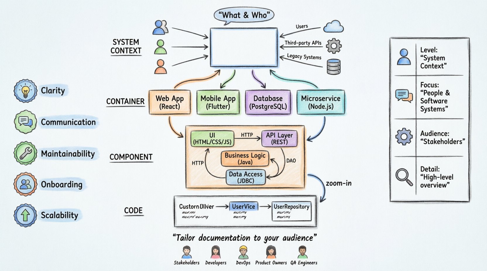
The C4 model is a hierarchy of diagrams used to document software architecture. It was created to address the common problem of creating diagrams that are either too detailed or too abstract. By organizing diagrams into four levels, teams can tailor their documentation to the needs of specific readers. This approach ensures that everyone involved understands the system without getting lost in unnecessary complexity.
At its core, the C4 model is about abstraction. It encourages architects to think about systems from high-level contexts down to specific code implementations. This hierarchy helps in managing the cognitive load when discussing complex systems. It allows teams to zoom in or out as needed during meetings or planning sessions.
Why Use the C4 Model? 🤔
There are several reasons why teams adopt this model for their documentation:
- Clarity: It provides a clear separation of concerns. Each diagram type has a specific purpose.
- Communication: It creates a common language for architects and developers.
- Maintainability: It is easier to update diagrams when the structure is well-defined.
- Onboarding: New team members can grasp the system architecture quickly.
- Scalability: It works for small scripts and large distributed systems alike.
Unlike other modeling techniques that might get bogged down in syntax or specific tools, the C4 model focuses on the concepts. This makes it tool-agnostic. You can use any software to create these diagrams as long as you follow the conventions.
The Four Levels of the C4 Model 📉
The model consists of four distinct levels. Each level builds upon the previous one, adding more detail. Understanding the progression from level to level is key to using the model effectively.
1. System Context 🌍
The System Context diagram is the highest level view. It shows the software system as a single box. It then displays the people and other systems that interact with it. This diagram answers the question: “What does this system do, and who uses it?”
This level is crucial for stakeholders who need to understand the boundaries of the system. It defines the scope without getting into internal logic. For example, a customer relationship management system might interact with an email service and a payment gateway. The System Context diagram maps these relationships clearly.
Key elements include:
- Software System: Represented as a central box.
- Person: Users or administrators interacting with the system.
- Software System: External systems that the main system talks to.
- Relationships: Lines showing data flow or interaction between elements.
2. Container 📦
The Container diagram breaks down the single software system into containers. A container is a deployable unit of software. It could be a web application, a mobile app, a database, or a microservice. This level answers: “How is the system built?”
Containers are the boundary between the code inside and the outside world. They define the technologies used, such as a Java application, a Node.js server, or a PostgreSQL database. This level is vital for developers who need to understand the architecture of the deployment.
Important aspects of this level:
- Technology Stack: Identifying the runtime environment for each container.
- Responsibilities: What function does each container perform?
- Connections: How do containers communicate? (HTTP, gRPC, Messages).
3. Component ⚙️
The Component diagram zooms further into a single container. It shows the internal structure of that container. Components are logical groupings of functionality within a container. They are not physical files but rather modules of code.
This level is useful for developers working on specific parts of the system. It helps them understand how features are implemented without needing to read every line of code. It clarifies dependencies and responsibilities within the container.
Example components might include:
- User Interface: The front-end logic.
- API Layer: The interface for external requests.
- Business Logic: The core rules and calculations.
- Data Access: The layer that talks to the database.
4. Code 💻
The Code level is the lowest level. It shows classes and objects. While the C4 model does not encourage creating diagrams for every class, it acknowledges this level exists. This is typically generated from the code or used for very specific architectural reviews.
Most teams do not maintain these diagrams manually. They are often generated automatically. This level is for developers debugging specific issues or understanding intricate object interactions.
Comparison of C4 Levels 📋
Understanding the differences between levels helps in choosing the right diagram for the right audience. The table below summarizes the distinctions.
| Level | Focus | Audience | Detail Level |
|---|---|---|---|
| System Context | Boundaries & External Systems | Stakeholders, Architects | High |
| Container | Deployable Units | Developers, DevOps | Medium |
| Component | Internal Functionality | Developers, Architects | Low |
| Code | Classes & Objects | Developers | Very Low |
Creating Effective Diagrams 🎨
Creating diagrams requires discipline. It is easy to add too much information or too little. Here are guidelines for creating useful diagrams at each level.
Guidelines for System Context
- Keep the number of external systems manageable. If there are too many, consider splitting the view.
- Label relationships clearly. Indicate the type of data flowing between systems.
- Use standard symbols for people and systems to maintain consistency.
- Focus on the “what” and “who”, not the “how”.
Guidelines for Containers
- Group related functionality into logical containers.
- Specify the technology used for each container.
- Minimize the number of connections. Too many lines create a “spaghetti” diagram.
- Ensure every container serves a clear purpose within the system.
Guidelines for Components
- Group components by feature or domain.
- Use clear names that reflect their responsibility.
- Highlight critical paths or data flows.
- Avoid showing every single method or function.
Audience and Usage 👥
Different people read these diagrams for different reasons. Tailoring the content to the audience ensures the documentation is useful.
For Stakeholders and Managers
These individuals focus on business value and system boundaries. The System Context diagram is most relevant for them. They need to know what the system does and how it fits into the broader business ecosystem. They do not need to see database schemas or API endpoints.
For Developers and Engineers
Engineers need to understand how to build and maintain the system. The Container and Component diagrams are essential here. They need to know which services to call, what data formats are used, and how the code is organized. This level of detail helps in onboarding new engineers and designing new features.
For DevOps and Operations
Operations teams focus on deployment and reliability. The Container diagram provides the necessary details about infrastructure requirements. It shows which containers need to be running and how they connect. This helps in setting up monitoring and deployment pipelines.
Integration with Agile Processes 🔄
Agile methodologies emphasize working software over comprehensive documentation. However, this does not mean documentation is unnecessary. The C4 model fits well into agile workflows.
When starting a new project, the System Context diagram can be created during the planning phase. As development progresses, the Container and Component diagrams can be updated. This ensures the documentation evolves with the code.
Some teams adopt a “Docs as Code” approach. This means the diagrams are stored in the same repository as the source code. This allows for version control and collaboration. It ensures that documentation changes are reviewed alongside code changes.
Common Pitfalls to Avoid ⚠️
Even with a good framework, teams can make mistakes. Being aware of these pitfalls helps in maintaining high-quality documentation.
- Over-detailing: Creating diagrams that show every single variable or method. This makes the diagram unreadable and hard to maintain.
- Under-documenting: Skipping levels entirely. If you only have a System Context diagram, developers will struggle to understand the internals.
- Inconsistency: Using different symbols or naming conventions in different diagrams. This confuses readers.
- Stale Documentation: Letting diagrams become outdated as the code changes. This creates a false sense of security.
- Tool Dependency: Relying too heavily on a specific tool feature. Focus on the concepts, not the tool capabilities.
Maintaining the Documentation 🛠️
Documentation is a living artifact. It requires ongoing effort to keep it accurate. Here are strategies to maintain the C4 model documentation.
Regular Reviews: Schedule periodic reviews of the diagrams. This ensures they align with the current state of the system.
Automated Generation: Where possible, use tools to generate parts of the diagrams from the code. This reduces manual effort and increases accuracy.
Change Management: When a major architectural change occurs, update the diagrams immediately. Treat diagram updates as part of the definition of done.
Accessibility: Store diagrams in a place where everyone can access them. A shared wiki or repository is better than local files on individual machines.
Benefits of Adoption 🚀
Teams that adopt the C4 model often see tangible improvements in their workflow.
- Faster Onboarding: New hires can understand the system architecture in days rather than weeks.
- Better Design Decisions: Visualizing the architecture helps identify bottlenecks and risks early.
- Reduced Miscommunication: A shared visual language reduces misunderstandings between teams.
- Improved Knowledge Sharing: Documentation serves as a knowledge base that is not tied to specific individuals.
- Easier Refactoring: Understanding the boundaries helps in safely modifying existing code.
Final Thoughts 💭
The C4 model provides a practical framework for documenting software architecture. It balances detail and abstraction effectively. By focusing on the right levels of detail for different audiences, it facilitates better communication and understanding.
Implementing this model requires a shift in mindset. It is not just about drawing pictures; it is about thinking clearly about system structure. Teams should start small, perhaps with the System Context diagram, and expand from there.
Remember that the goal is clarity. If a diagram confuses more people than it helps, it needs to be revised. The C4 model is a tool to support your team, not a constraint to limit creativity. By following these guidelines, you can build a robust architecture documentation strategy that supports your software development lifecycle.
As systems continue to evolve, the need for clear, maintainable documentation will only grow. The C4 model stands as a reliable guide in this journey. It empowers teams to manage complexity and deliver value consistently.

