Structural modeling forms the backbone of any robust software architecture. While many are familiar with standard class diagrams, there exists a more granular tool for visualizing the internal composition of complex systems. This is the UML Composite Structure Diagram. It offers a view into the anatomy of a classifier, revealing how internal parts interact to deliver functionality. 🧩
Understanding this diagram type allows architects to define boundaries, interfaces, and connections within a single entity. This guide will walk you through the essential elements, construction steps, and best practices for creating these diagrams without relying on specific commercial tools. We will focus on the underlying principles that govern the modeling process.
📊 Understanding the Purpose
A Composite Structure Diagram is a structural diagram in the Unified Modeling Language (UML). Its primary function is to illustrate the internal structure of a classifier. In simpler terms, it answers the question: What is inside this class or component, and how do those internal pieces connect? ⚙️
Unlike a Class Diagram, which focuses on relationships between different classes, the Composite Structure Diagram zooms in. It shows:
- Parts: The structural elements contained within the classifier.
- Ports: Interaction points where the classifier communicates with the outside world.
- Connectors: The pathways linking parts to ports or to other parts.
This level of detail is crucial when dealing with high-level system designs where the internal wiring matters as much as the external interface. It bridges the gap between abstract logic and concrete implementation details.
🧩 Core Elements and Semantics
To build an accurate diagram, you must understand the specific vocabulary and constraints of the notation. Every element serves a distinct purpose in the structural definition.
1. Classifier and Parts
The main frame of the diagram represents the classifier being modeled. Inside this frame, you define Parts. A part is a structural feature of the classifier. It represents a specific component or sub-structure that resides within the whole.
- Multiplicity: Parts have multiplicities, indicating how many instances of the part exist (e.g., one, many).
- Visibility: Parts can be private, protected, or public, affecting how they can be accessed.
- Role Names: A part may play a specific role within the context of the classifier.
2. Ports
Ports are the interaction points. They are the interfaces through which the classifier interacts with its environment or communicates with other classifiers. Ports are essentially named interaction points.
- Provided Interfaces: Represented by a lollipop symbol (a circle on a line). This indicates functionality the part offers to the outside.
- Required Interfaces: Represented by a half-circle or socket symbol. This indicates functionality the part needs from the outside.
3. Connectors
Connectors establish the links between structural elements. There are two primary types of connectors used in this context:
- Assembly Connectors: These link a required interface on a part to a provided interface on another part. They define the binding between the needs of one component and the capabilities of another.
- Delegation Connectors: These link a port on the classifier to a port on a part. This allows the classifier to delegate requests made to its external port to the internal part.
4. Collaboration
A Collaboration is a behavioral element that defines a set of roles and their interactions. In a Composite Structure Diagram, a collaboration can be used to describe the behavior of a part or the composite itself. It adds context to how the structure behaves when messages are exchanged.
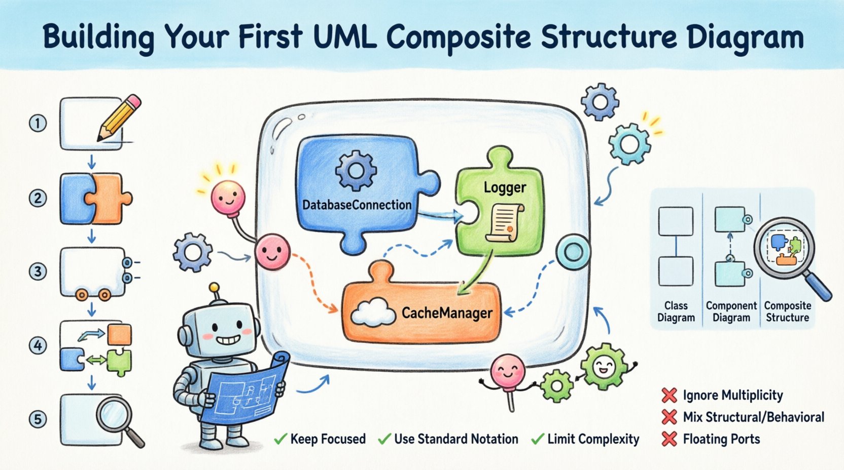
🛠️ Step-by-Step Construction Guide
Building this diagram requires a logical progression. You do not simply draw boxes; you model relationships. Follow this conceptual workflow to construct your diagram effectively.
Step 1: Define the Classifier
Start by identifying the specific classifier you wish to model. This could be a software class, a hardware module, or a system component. Draw the main rectangular frame representing this classifier. Label it clearly. 📝
- Ensure the name is unique within the current model context.
- Decide if this classifier is abstract or concrete, as this affects its instantiation.
Step 2: Identify Internal Parts
Next, determine the internal composition. What smaller units make up this classifier? These are your parts.
- List the dependencies or sub-components required for the classifier to function.
- Draw rectangles inside the classifier frame for each part.
- Label each part with its type (e.g.,
DatabaseConnection,Logger,CacheManager). - Specify the multiplicity for each part (e.g., 1, 0..1, *).
Step 3: Define Ports and Interfaces
Now, define how the classifier and its parts interact. This is where the logic of the system comes to life.
- External Ports: Draw ports on the border of the classifier frame. These are the public interfaces. Attach interface symbols (lollipop or socket) to define what is provided or required.
- Internal Ports: Draw ports on the internal parts. These are often hidden from the outside world but critical for internal wiring.
- Interface Types: Clearly distinguish between service interfaces (operations) and usage interfaces (attributes).
Step 4: Establish Connections
With parts and ports defined, you must wire them together. This is the most critical step for accuracy.
- Internal Wiring: Connect internal parts to each other using Assembly Connectors. Show how data flows from a logger to a database connection, for instance.
- Delegation: Connect external ports of the classifier to internal ports of parts using Delegation Connectors. This ensures that requests hitting the main interface are routed to the correct internal handler.
- Validation: Check that every required interface has a corresponding provided interface somewhere in the structure.
Step 5: Refine and Annotate
Finally, add notes and constraints to clarify complex behaviors.
- Use text boxes to explain specific interaction protocols.
- Add constraints using curly braces to specify conditions (e.g.,
{thread-safe}). - Review the diagram for symmetry and clarity. Ensure lines do not cross unnecessarily.
📋 Comparison: Composite vs. Class vs. Component
It is common to confuse the Composite Structure Diagram with Class or Component diagrams. Understanding the distinction prevents modeling errors.
| Diagram Type | Focus | Primary Elements | Typical Use Case |
|---|---|---|---|
| Class Diagram | Static structure of classes | Classes, Attributes, Operations | Defining data models and relationships between entities. |
| Component Diagram | Physical modules | Components, Interfaces, Nodes | Visualizing deployment and architectural layers. |
| Composite Structure Diagram | Internal structure of a classifier | Parts, Ports, Connectors, Roles | Detailing the internal wiring and interaction of a single complex entity. |
While a Class Diagram shows that Class A has a relationship with Class B, a Composite Structure Diagram shows that Class A contains an instance of Class B and routes messages to it. This distinction is vital for detailed design phases.
💡 Best Practices for Modeling
To ensure your diagrams remain readable and useful over time, adhere to these guidelines.
- Keep it Focused: Do not attempt to model an entire system in one diagram. Break it down by classifier. One diagram per major component is ideal.
- Use Standard Notation: Stick to the official UML shapes. Deviating from standard symbols confuses stakeholders.
- Limit Complexity: If a diagram becomes too crowded, consider extracting a sub-structure into a separate diagram or using a Collapsed Composite Structure.
- Consistent Naming: Ensure interface names on ports match the operations they define. Consistency aids automated code generation.
- Layering: Use nesting to show hierarchy. If a part contains other parts, draw the inner parts inside the outer part frame.
🚫 Common Pitfalls to Avoid
Even experienced modelers make mistakes. Being aware of these common errors will save you time during the review process.
- ❌ Ignoring Multiplicity: Forgetting to specify how many parts exist can lead to implementation errors. Always define 1, 0..1, or *.
- ❌ Mixing Structural and Behavioral: While collaborations define behavior, keep the focus on structure. Do not clutter the diagram with sequence diagram logic.
- ❌ Floating Ports: Ensure all ports are connected to either the classifier boundary or an internal part. Orphaned ports indicate incomplete wiring.
- ❌ Circular Dependencies: Avoid loops where parts depend on each other in a way that creates a cycle. This often indicates a design flaw.
🔗 Advanced Concepts: Roles and Roles
A role is a specific name for a part within the context of a relationship. A part is the general entity; the role is how it behaves in that specific instance.
- Contextual Usage: If a database part is used for reading, its role might be
Reader. If used for writing, the role isWriter. - Interface Binding: Roles often bind to specific interfaces. This clarifies which part handles which type of request.
- Refinement: You can refine a role to add specific constraints or behaviors that apply only to that interaction.
🔄 Iterating on the Design
Modeling is rarely a one-time activity. As requirements change, your Composite Structure Diagram must evolve.
- Review Frequency: Revisit the diagram during design reviews and refactoring sessions.
- Impact Analysis: Before changing an internal part, check which external ports depend on it.
- Documentation: Update accompanying text documentation to reflect structural changes.
- Version Control: Treat the diagram file as code. Commit changes with descriptive messages.
📝 Summary of Key Takeaways
The UML Composite Structure Diagram is a powerful tool for deep structural analysis. It moves beyond the surface level of relationships to expose the machinery of a classifier. By focusing on parts, ports, and connectors, you gain visibility into the internal logic that drives system behavior.
Key points to remember include:
- Use this diagram for internal structure, not just external relationships.
- Distinguish clearly between Assembly and Delegation connectors.
- Maintain strict adherence to UML notation for clarity.
- Keep diagrams modular to avoid visual clutter.
When applied correctly, this diagram type enhances communication between developers, architects, and testers. It provides a blueprint that is precise enough for implementation and clear enough for review. Whether you are designing complex enterprise software or embedded systems, the internal structure matters. Take the time to model it correctly.
🎓 Final Thoughts on Implementation
Implementing the concepts found in a Composite Structure Diagram often requires careful mapping to the chosen programming paradigm. In object-oriented programming, this maps directly to class composition and interface implementation. In service-oriented architectures, it maps to service contracts and internal message brokers.
The discipline of modeling internal structures forces you to think about coupling and cohesion. If a part requires too many interfaces, it may be too complex. If a part provides too little, it may not be reusable. The diagram serves as a visual audit of these architectural principles.
Start small. Model a single class with a few internal dependencies. Practice defining ports and connecting them. As you gain confidence, expand to larger components. The skill of structural modeling is built incrementally, much like the systems you will design.
By following the steps outlined in this guide, you are equipped to create diagrams that are not just visual aids, but functional specifications. They become the contract between design and code. Ensure that your models remain accurate as the system evolves, and they will remain a valuable asset throughout the project lifecycle.

