Software architecture documentation often suffers from a disconnect between design intent and implementation reality. For decades, Unified Modeling Language (UML) has been the standard for visualizing system structure. However, as systems grow in complexity and teams adopt agile methodologies, the traditional approach to diagramming has shown significant limitations. The C4 Model has emerged as a pragmatic alternative, focusing on abstraction and context rather than exhaustive detail. This guide explores the mechanics of the C4 Model, its advantages over legacy methods, and how it facilitates clarity in large-scale engineering environments.
The UML Bottleneck in Modern Development 🚧
UML was designed for a different era of software engineering. Its strength lay in its ability to specify every detail of a system before code was written. In waterfall environments, this made sense. Today, development is iterative. Systems evolve rapidly, and requirements shift frequently. When a diagram requires a level of detail that changes with every sprint, it becomes a liability rather than an asset.
The primary issues with traditional UML in modern contexts include:
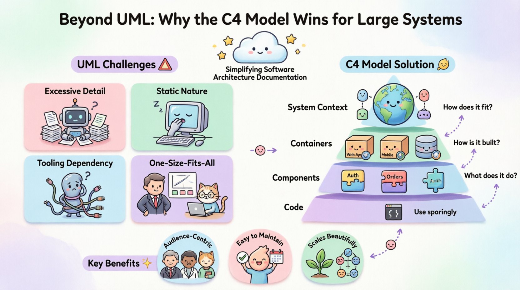
- Excessive Detail: Class diagrams often get bogged down in attributes, methods, and visibility modifiers. This obscures the high-level flow of data.
- Static Nature: UML diagrams often imply a fixed state. Modern systems are dynamic, distributed, and stateless in many respects.
- Tooling Dependency: Generating diagrams often requires specific tools that may not integrate well with code repositories.
- Lack of Audience Segmentation: A single diagram rarely serves both a C-level executive and a backend engineer simultaneously.
When documentation cannot keep pace with the code, it becomes outdated quickly. Teams stop trusting the diagrams, rendering them useless. The C4 Model addresses these friction points by enforcing a hierarchy of abstraction.
Introducing the C4 Model 🧩
The C4 Model is a structured approach to visualizing software architecture. It is not a tool, but a set of principles for creating diagrams at four distinct levels of abstraction. The goal is to communicate the architecture to different stakeholders without overwhelming them with irrelevant information.
The model is named after its four levels:
- Level 1: System Context
- Level 2: Container
- Level 3: Component
- Level 4: Code
Each level answers a specific question. By separating these concerns, architects can create diagrams that are easy to read, easy to maintain, and easy to update.
Deep Dive into the Four Levels 🔍
Level 1: System Context
At the highest level, the diagram describes the software system as a single box. The focus is on the boundaries of the system and its relationship to the outside world.
Key Elements:
- Software System: The central application or product.
- Users: People who interact with the system.
- External Systems: Other applications the system relies on or interacts with (e.g., payment gateways, third-party APIs).
This level answers the question: “How does this system fit into the wider ecosystem?” It is ideal for project managers, new team members, and business stakeholders who need to understand the scope without technical depth.
Level 2: Containers
A container is a distinct unit of deployment. It is a running process that holds the code. Examples include web applications, mobile apps, databases, and microservices.
Key Elements:
- Containers: The technologies running the software (e.g., React, PostgreSQL, Kubernetes).
- Technologies: The specific programming language or framework.
- Connections: How containers communicate (e.g., HTTP, TCP, gRPC).
This level answers the question: “How is the system built?” It provides enough technical detail for developers to understand the architecture without diving into code structure. It is crucial for onboarding and high-level technical planning.
Level 3: Components
Inside a container, there are components. A component is a logical grouping of functionality. It is a collection of related responsibilities within a container.
Key Elements:
- Components: Modules, packages, or classes that perform specific tasks (e.g., Authentication Service, Order Processor).
- Relationships: How components interact within the container.
This level answers the question: “What does the system do?” It bridges the gap between the high-level container view and the low-level code view. It is useful for developers working on specific parts of the system.
Level 4: Code
Level 4 diagrams describe the code structure. This includes classes, functions, and data structures.
Key Elements:
- Classes: The specific implementation details.
- Methods: The logic within the classes.
This level is rarely maintained as a standalone diagram because it changes too frequently. Instead, developers often rely on IDE capabilities or documentation generators for this level. The C4 Model acknowledges this level exists but recommends using it sparingly in documentation.
C4 vs. UML: A Direct Comparison 📊
Understanding the differences between the C4 Model and UML is essential for deciding which approach to adopt. The following table outlines the key distinctions.
| Feature | UML | C4 Model |
|---|---|---|
| Abstraction | Focused on structure and detail | Focused on context and audience |
| Maintenance | High effort, prone to obsolescence | Lower effort, hierarchical updates |
| Audience | Often generic, technical | Segmented by stakeholder role |
| Scope | Entire system at once | Progressive disclosure |
| Tooling | Often rigid, proprietary | Flexible, tool-agnostic |
UML attempts to describe the system in one go. C4 acknowledges that different people need to see the system differently. A C4 diagram for a stakeholder might be a Level 1 view, while a developer might look at a Level 2 or 3 view. This segmentation reduces cognitive load.
Scaling Architecture Documentation 📈
Large systems present unique challenges for documentation. As the number of microservices grows, the connectivity matrix becomes unmanageable. C4 provides a method to scale documentation without creating chaos.
Managing Complexity
When a system expands, adding new containers or components is common. In a UML approach, a change in one class might require redrawing a complex class diagram. In C4, a change in a component only requires updating the Level 3 diagram. The Level 1 and Level 2 diagrams often remain unchanged.
This modularity ensures that documentation scales linearly with the system, rather than exponentially.
Onboarding New Team Members
One of the most difficult tasks in large organizations is onboarding new engineers. They need to understand the system quickly. Providing a 50-page UML specification is overwhelming. Providing a set of C4 diagrams allows them to start at Level 1 and drill down as needed.
- Day 1: Review Level 1 to understand the system boundaries.
- Week 1: Review Level 2 to understand deployment topology.
- Month 1: Review Level 3 to understand code structure.
This progressive disclosure accelerates time-to-productivity.
Audience-Centric Communication 👥
Effective architecture documentation is not about showing everything; it is about showing the right information to the right person. The C4 Model inherently supports this by design.
For Business Stakeholders
Executives and product owners care about value and integration. They do not need to know which database engine is used. A Level 1 diagram serves them perfectly, showing how the system interacts with payment providers, CRM systems, and users.
For Developers
Engineers need to know how to deploy and maintain the system. Level 2 diagrams show the containers and their technologies. This helps them set up environments, configure networking, and understand dependencies.
For Architects
Architects need to see the logical structure. Level 3 diagrams reveal how responsibilities are split within containers. This helps in identifying coupling and cohesion issues before they become technical debt.
Implementation Strategies 🛠️
Adopting the C4 Model requires a shift in mindset. It is not about buying a new tool, but about changing how you document. Here are practical steps to integrate this approach.
- Start with Context: Before drawing anything, define the boundary of the system. Identify external dependencies.
- Define Containers: List the running processes. Do not group unrelated services into one container.
- Document Components: Break down containers into logical units. Avoid creating components that are too small (classes) or too large (entire containers).
- Keep it Updated: Integrate diagram updates into the definition of done for features. If the code changes, the diagram should reflect that change.
- Version Control: Store diagrams alongside code. This ensures they evolve with the project.
Common Pitfalls to Avoid ⚠️
Even with a structured model, teams often make mistakes. Being aware of these pitfalls helps maintain the integrity of the documentation.
Pitfall 1: Over-Engineering Level 4
Many teams try to create Level 4 diagrams for every class. This is a maintenance nightmare. Code documentation is better handled by code comments and static analysis tools. Reserve Level 4 for critical, complex algorithms that need visual explanation.
Pitfall 2: Ignoring Data Flows
Diagrams should not just show boxes and lines. They must show data. Arrows should indicate the direction of data flow. Is the data read-only? Is it bidirectional? Is it asynchronous? Labeling connections is essential.
Pitfall 3: Mixing Levels
Do not mix containers and components in the same diagram unless necessary. Keep the hierarchy clean. A Level 2 diagram should only show containers. A Level 3 diagram should only show components inside a specific container.
Pitfall 4: Static Maintenance
Do not treat diagrams as one-time artifacts. If a diagram is not updated during development, it will become false. Establish a culture where documentation is part of the development process.
Future-Proofing Your Documentation 🚀
Technology changes. Frameworks become obsolete. The C4 Model is resilient to these changes because it focuses on concepts rather than specific implementations.
- Technology Agnostic: Whether you use Java, Go, or Python, the container concept remains the same. The diagram does not need to change if you switch languages, as long as the container boundary remains.
- Scalability: The model works for monolithic applications and distributed microservices alike. It provides a consistent language for architecture regardless of scale.
- Community Support: The C4 Model is open and widely adopted. This ensures that knowledge and best practices are shared across the industry.
Final Considerations 🎯
Choosing the right documentation strategy is a decision that impacts the long-term health of a software project. While UML has served the industry well for decades, the demands of modern software delivery require a more flexible approach. The C4 Model offers a structured way to visualize architecture that respects the time of engineers and the needs of stakeholders.
By adopting a hierarchical approach, teams can maintain clarity without sacrificing detail. The separation of concerns allows for targeted communication. Executives see the big picture. Engineers see the implementation details. Everyone stays aligned.
The transition from UML to C4 is not about discarding technical rigor. It is about applying it where it matters most. It is about recognizing that a diagram is a communication tool, not a specification document. When diagrams serve their audience effectively, they become living artifacts that guide the development of complex systems.
Implementing the C4 Model requires discipline. It requires a commitment to keeping documentation current. However, the return on investment is significant. Reduced onboarding time, clearer decision-making, and a more maintainable codebase are the tangible benefits of adopting this structured approach.
For organizations dealing with large, distributed systems, the C4 Model is not just an option. It is a necessary evolution in how we document architecture. It brings order to complexity and ensures that the system design remains visible and understandable as the software grows.

