Software architecture relies heavily on visual communication. When teams collaborate on complex systems, the diagrams we create must convey precise structural relationships. A UML Composite Structure Diagram is a powerful tool for showing the internal structure of a classifier. However, without careful attention to detail, these diagrams can introduce confusion rather than clarity.
Ambiguity in design artifacts leads to implementation errors, rework, and misaligned expectations. This guide provides a deep dive into creating unambiguous Composite Structure Diagrams. We will explore parts, roles, ports, and interfaces, ensuring your diagrams serve their purpose as blueprints for development.
🧩 Understanding the Core Elements
Before refining your diagrams, you must understand the fundamental building blocks. Ambiguity often stems from misusing these elements or leaving their definitions implicit.
- Parts: These represent the internal components of a classifier. Think of them as the specific instances or roles held within the larger structure.
- Roles: A role defines how a part interacts with the outside world or other parts. It specifies the responsibilities a part fulfills within the composite.
- Ports: A port is a distinct interaction point. It acts as a boundary where the internal structure communicates with the external environment.
- Interfaces: Interfaces define the contract of behavior. They specify what operations are available without revealing implementation details.
When these elements are mixed up or left undefined, the diagram loses its value. For instance, treating a part as a standalone class rather than a component within a composite structure can obscure dependency flows.
🔗 Managing Connections and Associations
Connections in a Composite Structure Diagram illustrate how parts interact. Ambiguity frequently arises when the nature of these connections is unclear. Are they structural compositions? Are they dependencies? Do they imply aggregation?
Types of Links
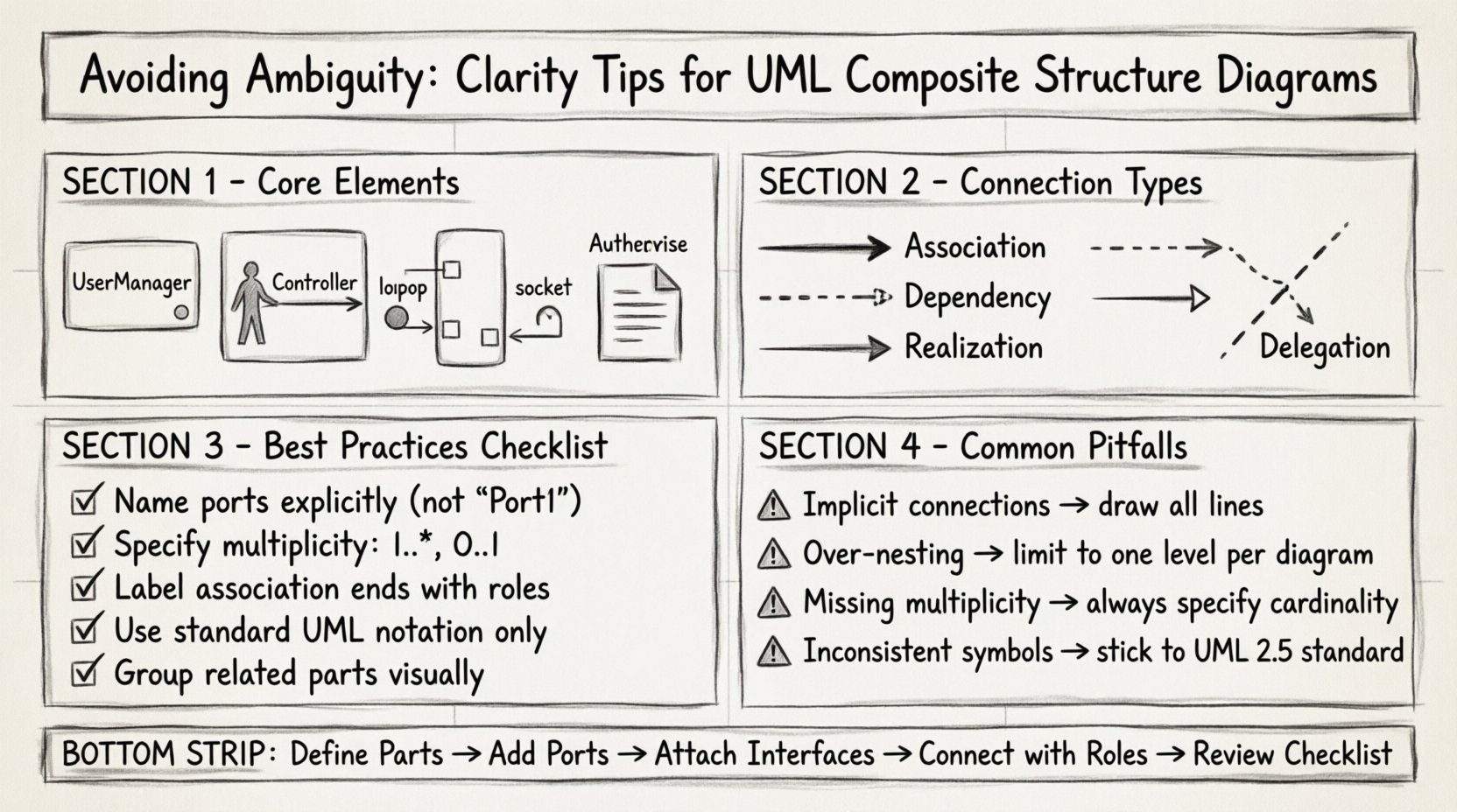
- Association: Indicates a structural relationship between two parts.
- Dependency: Shows that one part relies on another for functionality.
- Realization: Indicates that a part or port implements a specific interface.
- Delegation: Connects a port on the composite to a port on a part, hiding the internal complexity.
Using the wrong connector type can mislead developers about the lifecycle of objects. If a link implies a strong dependency but should be a loose association, the resulting code may be tightly coupled.
Visual Distinctions
Ensure visual distinctions are clear. Use standard UML notation for line endings and arrowheads. Do not invent custom symbols without a legend. Consistency is key to readability.
- Use solid lines for associations.
- Use dashed lines for dependencies.
- Use open arrowheads for realization.
🛠️ Ports and Interfaces: The Contract of Interaction
Ports are critical for defining boundaries. Without ports, it is unclear where external interaction occurs. Interfaces define the services available at those ports.
A common source of ambiguity is failing to specify the interface type at a port. Is the port a provided interface (lollipop notation) or a required interface (socket notation)?
Best Practices for Ports
- Name Explicitly: Every port should have a unique name within its scope. Avoid generic names like “Port1” or “Interface”.
- Specify Multiplicity: Indicate how many instances of the interface are needed. Use multiplicity notation (e.g., 1..*, 0..1) where applicable.
- Group Related Ports: If a part has multiple interaction points, group them visually to suggest a logical unit.
Interface Clarity
Interfaces should not be overloaded. A single interface should represent a cohesive set of behaviors. Splitting responsibilities across multiple interfaces makes the diagram easier to parse.
| Element | Definition | Common Pitfall |
|---|---|---|
| Provided Interface | Services offered by the part | Labeling it as a dependency instead of a realization |
| Required Interface | Services needed by the part | Failing to link it to a provider |
| Port | Physical or logical connection point | Using a port without an associated interface |
📐 Defining Parts and Roles Correctly
Parts are the structural components inside a composite. Roles define the specific behavior of a part in a specific context. Confusion often arises when a part is used in multiple contexts with different behaviors.
Role Naming
When a part plays a role, label the association end with the role name. This clarifies the part’s function at that specific connection point.
- Bad: An association line between two parts with no label.
- Good: An association line labeled “controller” on one end and “view” on the other.
Roles help answer the question: “What does this part do here?” rather than “What is this part?”. This distinction is vital for understanding dynamic behavior within a static structure.
Composite vs. Part
Ensure you distinguish between the composite classifier and its internal parts. A part can be a complex composite itself. This nesting capability allows for hierarchical modeling, but it requires clear boundaries.
Use bounding boxes to clearly delineate the interior of a composite. Do not let lines cross boundaries without a port. This visual containment reinforces the concept of encapsulation.
🚫 Common Ambiguity Traps
Even experienced designers fall into traps that obscure meaning. Identifying these patterns helps prevent errors in your own work.
1. Implicit Connections
Do not assume readers can infer connections from proximity. Draw the lines. If two parts interact, represent that interaction explicitly. Implicit relationships lead to race conditions in implementation.
2. Over-Nesting
While nesting is powerful, excessive nesting makes diagrams unreadable. If a composite contains too many internal parts, consider splitting the diagram into multiple views.
- Keep one level of nesting per diagram if possible.
- Use references to other diagrams for deep hierarchies.
3. Inconsistent Notation
Using non-standard symbols confuses readers. Stick to the UML 2.5 standard for composite structure diagrams. Deviations require a legend, which adds cognitive load.
4. Missing Multiplicity
Never assume cardinality. If a part can have multiple instances, state it. If it must have exactly one, state that. Ambiguity in multiplicity leads to memory management errors.
📝 Naming Conventions for Clarity
Naming is the first line of defense against ambiguity. A clear name reduces the need for explanatory text.
Part Naming
- Use noun phrases (e.g., “UserManager”, “DataStore”).
- Avoid verbs (e.g., “ProcessUser” is better as “Processor”).
- Ensure names reflect the lifecycle of the object.
Role Naming
- Use role-specific terms (e.g., “Supplier”, “Client”, “Observer”).
- Align role names with domain terminology.
Port Naming
- Name ports after the interface they expose or require.
- If multiple interfaces exist, use a composite name (e.g., “AuthPort”).
🔍 Review Checklist for Diagrams
Before finalizing a diagram, run it through this checklist. This ensures consistency and reduces the risk of misinterpretation.
- ☑️ Are all parts clearly defined within their composite bounds?
- ☑️ Do all ports have associated interfaces (provided or required)?
- ☑️ Are association ends labeled with role names where relevant?
- ☑️ Is the multiplicity specified on all associations?
- ☑️ Are delegation links used correctly to hide internal complexity?
- ☑️ Is the diagram readable without external documentation?
- ☑️ Are naming conventions consistent across the entire model?
- ☑️ Are there any crossed lines that can be reorganized for clarity?
🔄 Delegation and Encapsulation
Delegation ports allow a composite to expose a part’s functionality without exposing the part itself. This is a powerful mechanism for encapsulation.
When setting up delegation:
- Identify the internal part and its port.
- Identify the external port on the composite.
- Create a delegation connector between them.
- Ensure the interface types match.
If the interface types do not match, the diagram is invalid. This mismatch is a common source of ambiguity that compilers or validators will flag later.
🧠 Cognitive Load and Layout
The layout of the diagram affects how quickly a reader understands the structure. High cognitive load occurs when the visual arrangement contradicts the logical structure.
Layout Tips
- Group Related Parts: Place interacting parts close together.
- Minimize Crossings: Reorder parts to reduce line intersections.
- Directional Flow: Arrange parts to suggest a data or control flow direction (e.g., top to bottom).
- Consistent Spacing: Use even spacing to prevent visual clustering.
Consider the audience. A diagram for developers needs more detail than one for stakeholders. Adjust the level of abstraction accordingly.
🌐 Contextual Integration
A Composite Structure Diagram rarely exists in isolation. It is part of a larger system model. Ensure it aligns with Class Diagrams, Sequence Diagrams, and Component Diagrams.
- Class Diagram: Verify that the internal structure matches the class attributes.
- Sequence Diagram: Ensure the ports and interfaces match the message exchanges.
- Component Diagram: Confirm that the composite maps to a deployable unit.
Inconsistencies between these diagrams are a major source of ambiguity. If a class diagram shows a property that is not represented in the composite structure, the reader must guess the relationship.
📉 Handling Complexity
As systems grow, diagrams become complex. Techniques are needed to manage this complexity without losing clarity.
Fragmentation
Break large composites into smaller, manageable diagrams. Use a “Summary View” to show the high-level structure, and detail diagrams for specific subsystems.
References
Use references to link to other diagrams. This keeps the current diagram focused while acknowledging the broader context.
Annotations
Use notes sparingly. If a diagram requires extensive notes to be understood, the visual structure itself is likely flawed. Prefer clarity in the drawing over explanation in the text.
🛡️ Security and Visibility
Visibility modifiers (public, private, protected) apply to parts and ports as well. Omitting these can lead to ambiguity about access control.
- Public: Accessible from anywhere.
- Private: Accessible only within the composite.
- Protected: Accessible within the composite and subclasses.
Mark visibility explicitly on the diagram. Do not rely on implicit assumptions. This is crucial for security audits and code reviews.
🔧 Maintenance and Evolution
Diagrams must evolve with the software. Ambiguity often creeps in when diagrams are not updated alongside code changes.
- Update diagrams during refactoring.
- Remove obsolete parts and ports.
- Review diagrams before feature additions.
A stale diagram is a liability. It suggests a lack of discipline in the engineering process. Keeping diagrams current ensures they remain a source of truth.
🎯 Summary of Key Takeaways
Creating a clear UML Composite Structure Diagram requires discipline and attention to detail. By adhering to standard notation, defining roles explicitly, and managing visual complexity, you can eliminate ambiguity.
Focus on these core principles:
- Use standard UML symbols consistently.
- Define ports and interfaces clearly.
- Label associations with role names.
- Specify multiplicity for all relationships.
- Review against other model elements.
When you prioritize clarity, you reduce the cognitive load on your team. This leads to faster implementation, fewer bugs, and a more maintainable system. The effort spent on refining your diagrams pays dividends in the quality of the final product.

